Nissan Quest E52. Manual - part 768
HAC-202
< DTC/CIRCUIT DIAGNOSIS >
[MANUAL AIR CONDITIONING]
REAR A/C CONTROL COMMUNICATION SIGNAL
NAL
1.
Turn ignition switch OFF.
2.
Disconnect A/C amp. connector.
3.
Turn ignition switch ON.
4.
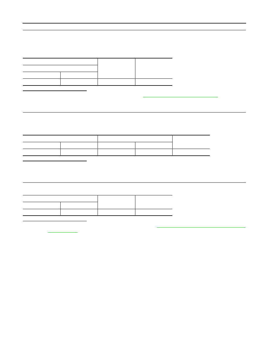
Check voltage between A/C amp. harness connector and ground.
Is the inspection result normal?
YES
>> Replace front A/C control (A/C amp.). Refer to
HAC-238, "Removal and Installation"
.
NO
>> GO TO 6.
6.
CHECK COMMUNICATION SIGNAL (A/C AMP.
→
REAR A/C CONTROL) CIRCUIT FOR OPEN
1.
Turn ignition switch OFF.
2.
Disconnect rear A/C control connector.
3.
Check continuity between rear A/C control harness connector and A/C amp. harness connector.
Is the inspection result normal?
YES
>> GO TO 7.
NO
>> Repair harness or connector.
7.
CHECK COMMUNICATION SIGNAL (A/C AMP.
→
REAR A/C CONTROL) CIRCUIT FOR SHORT
Check continuity between rear A/C control harness connector and ground.
Is the inspection result normal?
YES
>> Check rear A/C control power supply circuit. Refer to
HAC-200, "REAR A/C CONTROL : Diagno-
NO
>> Repair harness or connector.
+
−
Voltage
(Approx.)
A/C amp.
Connector
Terminal
M49
32
Ground
5 V
Rear A/C control
A/C amp.
Continuity
Connector
Terminal
Connector
Terminal
R16
9
M49
32
Existed
Rear A/C control
—
Continuity
Connector
Terminal
R16
9
Ground
Not existed