Nissan Quest E52. Manual - part 761


  Index      Nissan     Nissan Quest E52 (2011-2014 year) - Service and Repair Manual


Search            


Content   ..  759  760  761  762   ..


Nissan Quest E52. Manual - part 761


HAC-174

< SYSTEM DESCRIPTION >

[MANUAL AIR CONDITIONING]

DIAGNOSIS SYSTEM (A/C AMP.)

DIAGNOSIS SYSTEM (A/C AMP.)

Description

INFOID:0000000009652637

Air conditioning system performs self-diagnosis, operation check, and function diagnosis using diagnosis func-
tion of each control unit.

On Board Diagnosis Function

INFOID:0000000009652638

ON BOARD DIAGNOSIS ITEM

On board diagnosis function of A/C amp. consists of steps 1. Indicator check can be performed by step 1.

METHOD OF STARTING

Self-diagnosis Mode Entry

The self-diagnosis is started by pressing the ON·OFF switch for 5 seconds or more within 10 seconds after
starting engine. 

Self-diagnosis Cancellation

By pressing DEF switch or turning ignition switch OFF, the self-diagnosis is canceled. 

STEP 1: INDICATOR CHECK

Description

Front A/C control (switch indicator and display) and rear A/C control (display) indication are checked. 
Normal: All switch indicator and display indication are turned ON.
Malfunction: Malfunctioning part indicator is not turned ON.
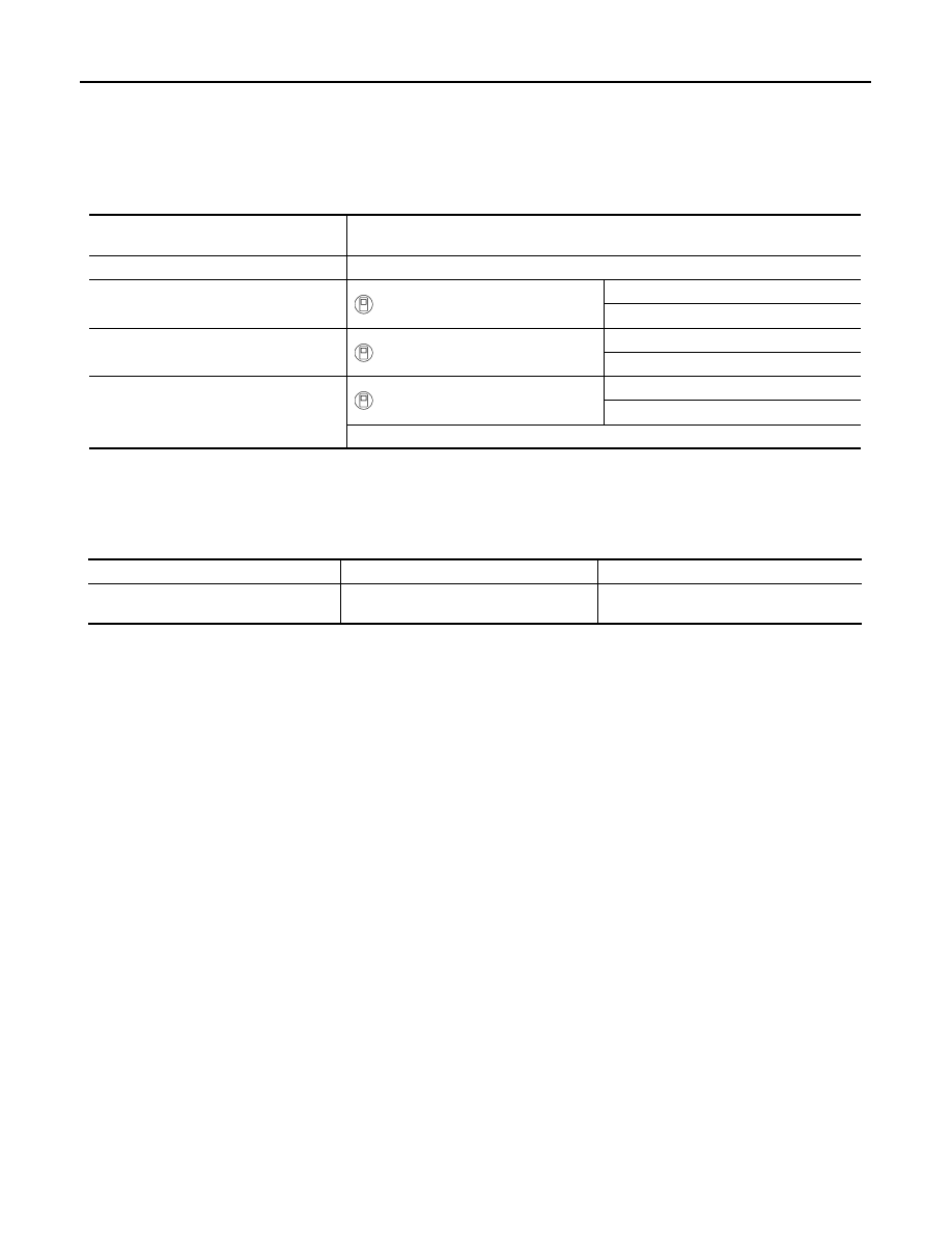
ECU

Diagnostic item

(CONSULT)

A/C amp.

On board diagnosis function

BCM

BCM-AIR CONDITIONER

Self Diagnostic Result

Data Monitor

ECM

ENGINE

Self Diagnostic Result

Data Monitor

IPDM E/R

IPDM E/R

Self Diagnostic Result

Data Monitor

Auto active test

Diagnosis item

Diagnosis content

Diagnosis part

STEP 1:
Indicator check

Switch indicator and display indication are 
checked.

• Front A/C control (A/C amp.)
• Rear A/C control

DIAGNOSIS SYSTEM (BCM)

HAC-175

< SYSTEM DESCRIPTION >

[MANUAL AIR CONDITIONING]

C

D

E

F

G

H

J

K

L

M

A

B

HAC

N

O

P

DIAGNOSIS SYSTEM (BCM)

COMMON ITEM

COMMON ITEM : CONSULT Function (BCM - COMMON ITEM)

INFOID:0000000009652639

APPLICATION ITEM

CONSULT performs the following functions via CAN communication with BCM.

SYSTEM APPLICATION

BCM can perform the following functions for each system.
NOTE:
It can perform the diagnosis modes except the following for all sub system selection items.

×

: Applicable item

NOTE:

*: For models with automatic air conditioning control system, this diagnosis mode is not used.

FREEZE FRAME DATA (FFD)

The BCM records the following vehicle condition at the time a particular DTC is detected, and displays on
CONSULT.

Diagnosis mode

Function Description

Work Support

Changes the setting for each system function.

Self Diagnostic Result

Displays the diagnosis results judged by BCM.

CAN Diag Support Monitor

Monitors the reception status of CAN communication viewed from BCM.

Data Monitor

The BCM input/output signals are displayed.

Active Test

The signals used to activate each device are forcibly supplied from BCM.

Ecu Identification

The BCM part number is displayed.

Configuration

• Read and save the vehicle specification.
• Write the vehicle specification when replacing BCM.

System

Sub system selection item

Diagnosis mode

Work Support

Data Monitor

Active Test

Door lock

DOOR LOCK

×

×

×

Rear window defogger

REAR DEFOGGER

×

×

Warning chime

BUZZER

×

×

Interior room lamp control system

INT LAMP

×

×

×

Exterior lamp

HEAD LAMP

×

×

×

Wiper and washer

WIPER

×

×

×

Turn signal and hazard warning lamps

FLASHER

×

×

×

Air conditioning control system

AIR CONDITONER

×

×

*

• Intelligent Key system
• Engine start system

INTELLIGENT KEY

×

×

×

Combination switch

COMB SW

×

Body control system

BCM

×

NVIS

IMMU

×

×

×

Interior room lamp battery saver

BATTERY SAVER

×

×

×

Back door open

TRUNK

×

Vehicle security system

THEFT ALM

×

×

×

RAP system

RETAINED PWR

×

Signal buffer system

SIGNAL BUFFER

×

×

TPMS

AIR PRESSURE MONITOR

×

×

×

HAC-176

< SYSTEM DESCRIPTION >

[MANUAL AIR CONDITIONING]

DIAGNOSIS SYSTEM (BCM)

NOTE:

*: Refer to the following for details of the power supply position.

• OFF (OFF, LOCK): Ignition switch OFF

• ACC: Ignition switch ACC

• IGN: Ignition switch ON with engine stopped

• RUN: Ignition switch ON with engine running

• CRANK: At engine cranking

Power supply position shifts to “OFF (LOCK)” from “OFF (OFF)”, when ignition switch is in the OFF position, shift position is in the P
position, and any of the following conditions are met.

• Closing door

• Opening door

• Door is locked using door request switch

• Door is locked using Intelligent Key

The power supply position shifts to “ACC” when the push-button ignition switch (push switch) is pushed at “OFF (LOCK)”.

AIR CONDITIONER

CONSULT screen item

Indication/Unit

Description

Vehicle Speed

km/h

Vehicle speed of the moment a particular DTC is detected

Odo/Trip Meter

km

Total mileage (Odometer value) of the moment a particular DTC is detected

Vehicle Condition

SLEEP>LOCK

Power position status of 
the moment a particular 
DTC is detected*

While turning BCM status from low power consumption mode to 
normal mode [Power supply position is OFF (LOCK)]

SLEEP>OFF

While turning BCM status from low power consumption mode to 
normal mode [Power supply position is OFF (OFF)]

LOCK>ACC

While turning power supply position from OFF (LOCK) to ACC

ACC>ON

While turning power supply position from ACC to ON

RUN>ACC

While turning power supply position from RUN to ACC (Except 
emergency stop operation)

CRANK>RUN

While turning power supply position from CRANK to RUN

RUN>URGENT

While turning power supply position from RUN to ACC (Emergen-
cy stop operation)

ACC>OFF

While turning power supply position from ACC to OFF (OFF)

OFF>LOCK

While turning power supply position from OFF (OFF) to OFF 
(LOCK)

OFF>ACC

While turning power supply position from OFF (OFF) to ACC

ON>CRANK

While turning power supply position from ON to CRANK

OFF>SLEEP

While turning BCM status from normal mode [Power supply posi-
tion is OFF (OFF)] to low power consumption mode

LOCK>SLEEP

While turning BCM status from normal mode [Power supply posi-
tion is OFF (LOCK)] to low power consumption mode

LOCK

Power supply position is OFF (LOCK)

OFF

Power supply position is OFF (OFF)

ACC

Power supply position is ACC

ON

Power supply position is ON

ENGINE RUN

Power supply position is RUN

CRANKING

Power supply position is CRANK

IGN Counter

0 - 39

The number of times that ignition switch is turned ON after DTC is detected
• The number is 0 when a malfunction is detected now.
• The number increases like 1 

 2 

 3...38 

 39 after returning to the normal condition 

whenever ignition switch OFF 

 ON.

• The number is fixed to 39 until the self-diagnosis results are erased if it is over 39.

DIAGNOSIS SYSTEM (BCM)

HAC-177

< SYSTEM DESCRIPTION >

[MANUAL AIR CONDITIONING]

C

D

E

F

G

H

J

K

L

M

A

B

HAC

N

O

P

AIR CONDITIONER : CONSULT Function (BCM - AIR CONDITIONER) (Manual A/C)

INFOID:0000000009652640

DATA MONITOR

NOTE:
The following table includes information (items) inapplicable to this vehicle. For information (items) applicable
to this vehicle, refer to CONSULT display items.

Display Item List

Monitor Item [Unit]

Contents

FAN ON SIG

[On/Off]

Displays the status of blower fan ON signal received from A/C amp.

AIR COND SW

[On/Off]

Displays the status of A/C ON signal received from A/C amp.


Content   ..  759  760  761  762   ..