Nissan Quest E52. Manual - part 750


  Index      Nissan     Nissan Quest E52 (2011-2014 year) - Service and Repair Manual


Search            


Content   ..  748  749  750  751   ..


Nissan Quest E52. Manual - part 750


HAC-130

< DTC/CIRCUIT DIAGNOSIS >

[AUTOMATIC AIR CONDITIONING]

REAR BLOWER MOTOR

1.

Remove rear blower motor. Refer to 

VTL-18, "REAR BLOWER MOTOR : Removal and Installation"

.

2.

Check that there is not any mixing foreign object in the rear blower motor. 

Is the inspection result normal?

YES

>> GO TO 2.

NO

>> Replace rear blower motor. Refer to 

VTL-18, "REAR BLOWER MOTOR : Removal and Installa-

tion"

.

2.

CHECK REAR BLOWER MOTOR-II

Check that there is not breakage or damage in the rear blower motor. 
Is the inspection result normal?

YES

>> GO TO 3.

NO

>> Replace rear blower motor. Refer to 

VTL-18, "REAR BLOWER MOTOR : Removal and Installa-

tion"

.

3.

CHECK REAR BLOWER MOTOR-III

Check that rear blower motor turns smoothly. 
Is the inspection result normal?

YES

>> INSPECTION END

NO

>> Replace rear blower motor. Refer to 

VTL-18, "REAR BLOWER MOTOR : Removal and Installa-

tion"

.

Component Inspection (Rear Blower Relay)

INFOID:0000000009652577

1.

CHECK REAR BLOWER RELAY

1.

Remove rear blower relay. Refer to 

PG-81, "Fuse and Fusible Link Arrangement"
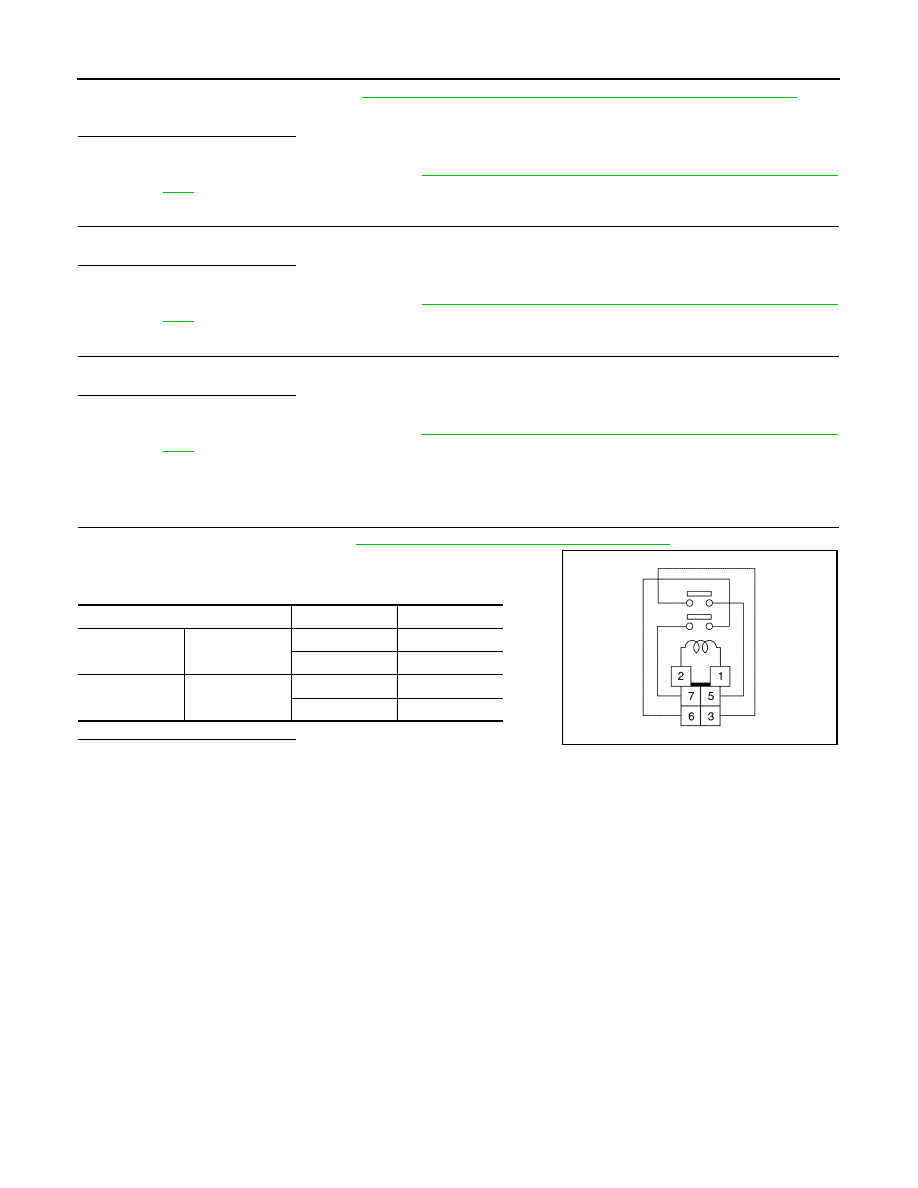
.

2.

Check continuity between rear blower relay terminal 3 and 5,
then 6 and 7 when voltage is supplied between terminal 1 and 2. 

Is the inspection result normal?

YES

>> INSPECTION END

NO

>> Replace rear blower relay.

Terminal

Voltage

Continuity

3

5

ON

Existed

OFF

Not existed

6

7

ON

Existed

OFF

Not existed

JMIIA1869ZZ

MAGNET CLUTCH

HAC-131

< DTC/CIRCUIT DIAGNOSIS >

[AUTOMATIC AIR CONDITIONING]

C

D

E

F

G

H

J

K

L

M

A

B

HAC

N

O

P

MAGNET CLUTCH

Component Function Check

INFOID:0000000009652578

1.

CHECK MAGNET CLUTCH OPERATION

Perform auto active test of IPDM E/R. Refer to 

PCS-11, "Diagnosis Description"

Does it operate normally?

YES

>> INSPECTION END

NO

>> Refer to 

HAC-131, "Diagnosis Procedure"

.

Diagnosis Procedure

INFOID:0000000009652579

1.

CHECK MAGNET CLUTCH

1.

Turn ignition switch OFF. 

2.

Disconnect compressor connector. 

3.

Directly apply battery voltage to the magnet clutch. Check for operation visually and by sound. 

Does it operate normally?

YES

>> GO TO 2.

NO

>> GO TO 4.

2.

CHECK FUSE

Check 10A fuse (No. 49, located in IPDM E/R). 
NOTE:
Refer to 

PG-82, "Fuse, Connector and Terminal Arrangement"

.

Is the inspection result normal?

YES

>> GO TO 3.

NO

>> Replace the blown fuse after repairing the affected circuit if a fuse is blown. 

3.

CHECK MAGNET CLUTCH POWER SUPPLY CIRCUIT FOR OPEN

1.

Disconnect IPDM E/R connector.

2.

Check continuity between IPDM E/R harness connector and compressor harness connector. 

Is the inspection result normal?

YES

>> Replace IPDM E/R. Refer to 

PCS-36, "Removal and Installation"

.

NO

>> Repair harness or connector.

4.

CHECK MAGNET CLUTCH GROUND CIRCUIT FOR OPEN

Check continuity between compressor harness connector and ground. 

Is the inspection result normal?

YES

>> Replace magnet clutch. Refer to 

HA-32, "MAGNET CLUTCH : Removal and Installation of Com-

pressor Clutch"

.

NO

>> Repair harness or connector. 

IPDM E/R

Compressor

Continuity

Connector

Terminal

Connector

Terminal

F12

48

F18

1

Existed

Compressor

Continuity

Connector

Terminal

F18

2

Ground

Existed

HAC-132

< DTC/CIRCUIT DIAGNOSIS >

[AUTOMATIC AIR CONDITIONING]

IONIZER

IONIZER

Diagnosis Procedure

INFOID:0000000009652580

1.

CHECK IONIZER POWER SUPPLY

1.

Turn ignition switch OFF.

2.

Disconnect ionizer connector.

3.

Turn ignition switch ON.

4.

Check voltage between ionizer harness connector and ground.

Is the inspection result normal?

YES

>> GO TO 2.

NO

>> Repair harness or connector between ionizer and fuse block (J/B).

2.

CHECK IONIZER GROUND CIRCUIT FOR OPEN

1.

Turn ignition switch OFF.

2.

Check continuity between ionizer harness connector and ground.

Is the inspection result normal?

YES

>> GO TO 3.

NO

>> Repair harness or connector.

3.

CHECK IONIZER (ON/OFF) CONTROL SIGNAL

1.

Connect ionizer connector.

2.

Disconnect A/C auto amp. connector.

3.

Turn ignition switch ON.

4.

Check voltage between A/C auto amp. harness connector and ground.

Is the inspection result normal?

YES

>> Replace front A/C control (A/C auto amp.). Refer to 

HAC-143, "Removal and Installation"

.

NO

>> GO TO 4.

4.

CHECK IONIZER (ON/OFF) CONTROL SIGNAL CIRCUIT FOR OPEN

1.

Turn ignition switch OFF.

2.

Disconnect ionizer connector.

3.

Check continuity between A/C auto amp. harness connector and ionizer harness connector.

Is the inspection result normal?

+

Voltage

Ionizer

Connector

Terminal

M64

1

Ground

11 – 14 V

Ionizer

Continuity

Connector

Terminal

M64

3

Ground

Existed

+

Voltage

A/C auto amp.

Connector

Terminal

M50

15

Ground

9.5 – 13.5 V

Ionizer

A/C auto amp.

Continuity

Connector

Terminal

Connector

Terminal

M64

4

M50

15

Existed

IONIZER

HAC-133

< DTC/CIRCUIT DIAGNOSIS >

[AUTOMATIC AIR CONDITIONING]

C

D

E

F

G

H

J

K

L

M

A

B

HAC

N

O

P

YES

>> GO TO 5.

NO

>> Repair harness or connector.

5.

CHECK IONIZER (ON/OFF) CONTROL SIGNAL CIRCUIT FOR SHORT

Check continuity between A/C auto amp. harness connector and ground.

Is the inspection result normal?

YES

>> Replace ionizer. Refer to 

HAC-155, "Removal and Installation"

.

NO

>> Repair harness or connector.

Ionizer

Continuity

Connector

Terminal

M64

4

Ground

Not existed


Content   ..  748  749  750  751   ..