Nissan Quest E52. Manual - part 684
FRONT STABILIZER
FSU-15
< REMOVAL AND INSTALLATION >
C
D
F
G
H
I
J
K
L
M
A
B
FSU
N
O
P
FRONT STABILIZER
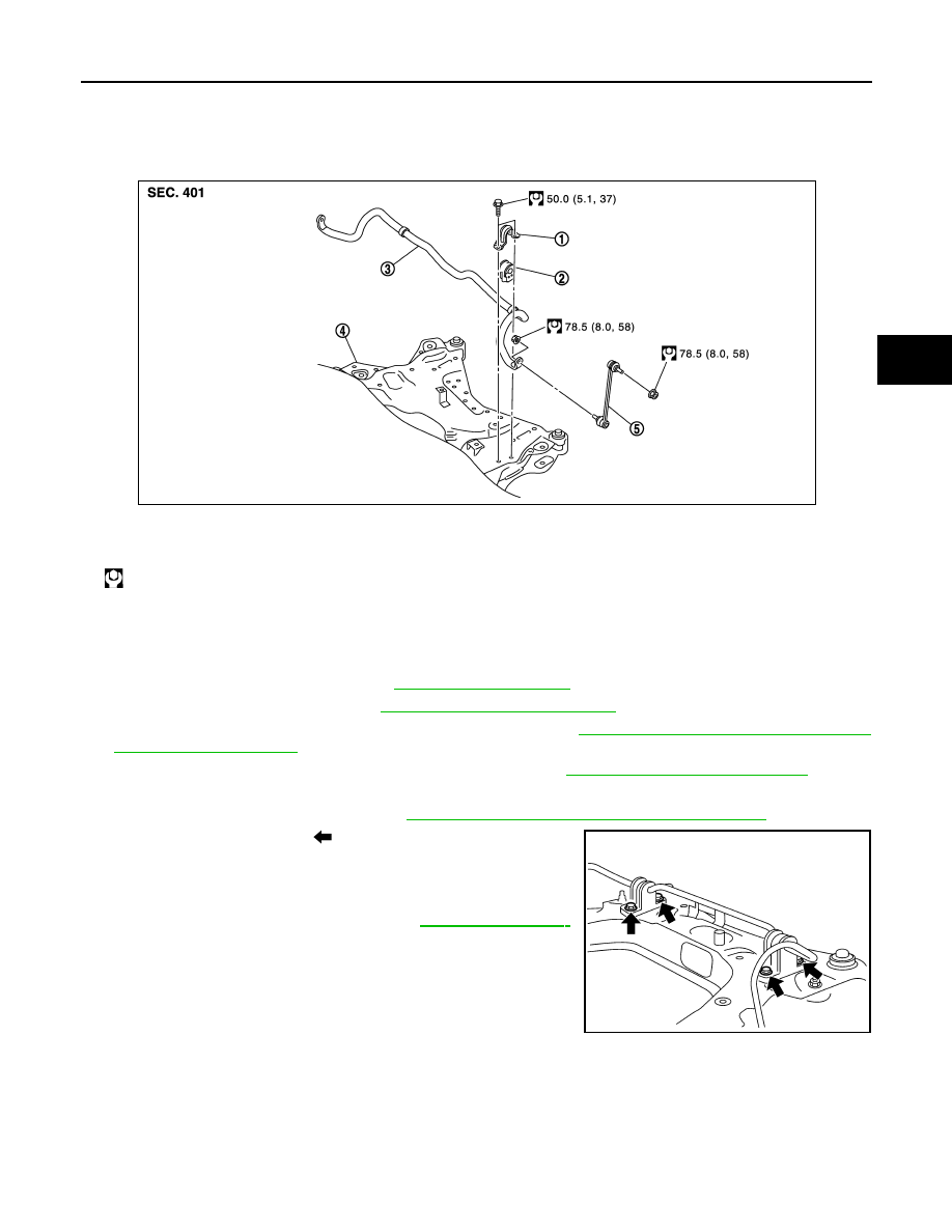
Exploded View
INFOID:0000000009650675
Removal and Installation
INFOID:0000000009650676
REMOVAL
1.
Remove tires with power tool. Refer to
.
2.
Remove exhaust front tube. Refer to
EX-6, "Removal and Installation"
3.
Remove wheel sensor harness from strut assembly. Refer to
BRC-119, "FRONT WHEEL SENSOR :
.
4.
Separate steering outer socket from steering knuckle. Refer to
ST-22, "Removal and Installation"
.
5.
Remove stabilizer connecting rod.
6.
Remove drive shaft (right side). Refer to
FAX-19, "RIGHT SIDE : Removal and Installation"
.
7.
Remove mounting bolts (
) of stabilizer clamp, and then
remove stabilizer clamp and stabilizer bushing from front sus-
pension member.
8.
Remove stabilizer bar.
9.
Perform inspection after removal. Refer to
INSTALLATION
Note the following, and install in the reverse order of removal.
1.
Stabilizer clamp
2.
Stabilizer bushing
3.
Stabilizer bar
4.
Front suspension member
5.
Stabilizer connecting rod
: N·m (kg-m, ft-lb)
JPEIA0164GB
WEIA0182E