Nissan Quest E52. Manual - part 677
FUEL LEVEL SENSOR UNIT, FUEL FILTER AND FUEL PUMP ASSEMBLY
FL-5
< REMOVAL AND INSTALLATION >
C
D
E
F
G
H
I
J
K
L
M
A
FL
N
P
O
REMOVAL AND INSTALLATION
FUEL LEVEL SENSOR UNIT, FUEL FILTER AND FUEL PUMP ASSEMBLY
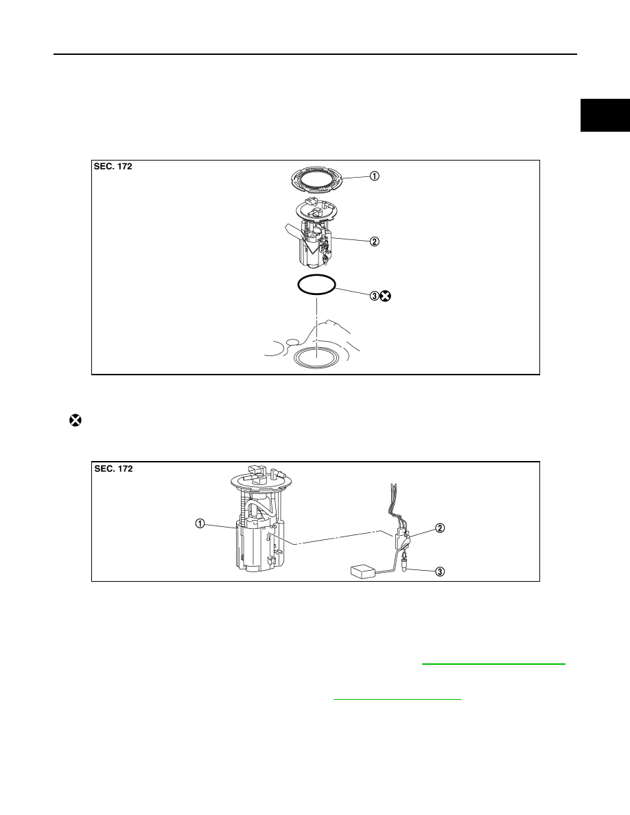
Exploded View
INFOID:0000000009653258
REMOVAL
DISASSEMBLY
Removal and Installation
INFOID:0000000009653259
WARNING:
Read “General Precautions” when working on the fuel system. Refer to
.
REMOVAL
1.
Release the fuel pressure from the fuel lines. Refer to
.
2.
Check fuel level on a level ground. If the fuel level is 7/8 of the fuel tank (full or nearly full), draw appropri-
ate amount of fuel from the fuel tank.
• In the event of malfunction in fuel pump, insert a hose measuring 20mm (0.79 in) in diameter into the
filler opening to draw approximately 20 liters fuel.
1.
Retainer
2.
Fuel level sensor unit, fuel filter and
fuel pump assembly
3.
Seal packing
: Always replace after every disassembly.
JPBIA4663ZZ
1.
Fuel filter and fuel pump assembly
2.
Fuel level sensor unit
3.
Fuel tank temperature sensor
JPBIA5300ZZ
Guideline
: Draw approximately 20 liters from a full-tank condition.