Nissan Quest E52. Manual - part 647


  Index      Nissan     Nissan Quest E52 (2011-2014 year) - Service and Repair Manual


Search            


Content   ..  645  646  647  648   ..


Nissan Quest E52. Manual - part 647


EXL-192

< DTC/CIRCUIT DIAGNOSIS >

[HALOGEN TYPE]

FRONT FOG LAMP CIRCUIT

NO

>> Repair or replace harness.

4.

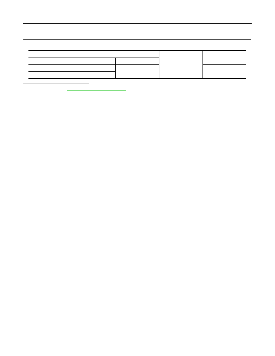
CHECK FRONT FOG LAMP GROUND CIRCUIT OPEN CIRCUIT

Check continuity between front fog lamp harness connector and ground.

Is the inspection result normal?

YES

>> Refer to 

GI-42, "Intermittent Incident"

.

NO

>> Repair or replace harness.

Front fog lamp

Ground

Continuity

Connector

Terminal

RH

E402

2

Existed

LH

E331

OPTICAL SENSOR

EXL-193

< DTC/CIRCUIT DIAGNOSIS >

[HALOGEN TYPE]

C

D

E

F

G

H

I

J

K

M

A

B

EXL

N

O

P

OPTICAL SENSOR

Component Function Check

INFOID:0000000009653170

1.

CHECK OPTICAL SENSOR SIGNAL BY CONSULT

CONSULT DATA MONITOR

1.

Turn ignition switch ON.

2.

Select “OPTISEN (DTCT)” of BCM (HEADLAMP) data monitor item.

3.

Turn lighting switch AUTO.

4.

With the optical sensor illuminating, check the monitor status. 

*: Illuminates the optical sensor. The value may be less than the standard value if brightness is weak.

Is the inspection result normal?

YES

>> Optical sensor is normal.

NO

>> Refer to 

EXL-193, "Diagnosis Procedure"

.

Diagnosis Procedure

INFOID:0000000009653171

1.

CHECK OPTICAL SENSOR POWER SUPPLY INPUT

1.

Turn ignition switch ON.

2.

Turn lighting switch AUTO.

3.

Check voltage between optical sensor harness connector and ground.

Is the inspection result normal?

YES

>> GO TO 2.

NO

>> GO TO 4.

2.

CHECK OPTICAL SENSOR GROUND INPUT

Check voltage between optical sensor harness connector and ground.

Is the inspection result normal?

YES

>> GO TO 3.

NO

>> GO TO 6.

3.

CHECK OPTICAL SENSOR SIGNAL OUTPUT

 With illuminating the optical sensor, check voltage between optical sensor harness connector and ground.

Monitor item

Condition

Voltage (Approx.)

OPTISEN (DTCT)

Optical sensor

When illuminating

3.1 V or more *

When shutting off light

0.6 V or less

(+)

(

)

Voltage

(Approx.)

Optical sensor

Connector

Terminal

M17

1

Ground

5 V

(+)

(

)

Voltage

(Approx.)

Optical sensor

Connector

Terminal

M17

3

Ground

0 V

EXL-194

< DTC/CIRCUIT DIAGNOSIS >

[HALOGEN TYPE]

OPTICAL SENSOR

*: Illuminate the optical sensor. The value may be less than the standard if brightness is weak.

Is the inspection result normal?

YES

>> GO TO 7.

NO

>> Replace the optical sensor.

4.

CHECK OPTICAL SENSOR OPEN CIRCUIT

1.

Turn ignition switch OFF.

2.

Disconnect optical sensor connector and BCM connector.

3.

Check continuity between optical sensor harness connector and BCM harness connector.

Is the inspection result normal?

YES

>> GO TO 5.

NO

>> Repair or replace harness.

5.

CHECK OPTICAL SENSOR SHORT CIRCUIT

Check continuity between optical sensor harness connector and ground.

Is the inspection result normal?

YES

>> Replace BCM. Refer to 

BCS-98, "Removal and Installation"

.

NO

>> Repair or replace harness.

6.

CHECK OPTICAL SENSOR GROUND OPEN CIRCUIT

1.

Turn ignition switch OFF.

2.

Disconnect optical sensor connector and BCM connector.

3.

Check continuity between optical sensor harness connector and BCM harness connector.

Is the inspection result normal?

YES

>> Replace BCM. Refer to 

BCS-98, "Removal and Installation"

.

NO

>> Repair or replace harness.

7.

CHECK OPTICAL SENSOR SIGNAL OPEN CIRCUIT 

1.

Turn ignition switch OFF.

2.

Disconnect optical sensor connector and BCM connector.

3.

Check continuity between optical sensor harness connector and BCM harness connector.

(+)

(

)

Condition

Voltage

(Approx.)

Optical sensor

Connector

Terminal

M17

2

Ground

Optical sensor

When illuminating

3.1 V or more *

When shutting off light

0.6 V or less

Optical sensor

BCM

Continuity

Connector

Terminal

Connector

Terminal

M17

1

M121

17

Existed

Optical sensor

Ground

Continuity

Connector

Terminal

M17

1

Not existed

Optical sensor

BCM

Continuity

Connector

Terminal

Connector

Terminal

M17

3

M121

18

Existed

OPTICAL SENSOR

EXL-195

< DTC/CIRCUIT DIAGNOSIS >

[HALOGEN TYPE]

C

D

E

F

G

H

I

J

K

M

A

B

EXL

N

O

P

Is the inspection result normal?

YES

>> GO TO 8.

NO

>> Repair or replace harness.

8.

CHECK OPTICAL SENSOR SHORT CIRCUIT

Check continuity between optical sensor harness connector and ground.

Is the inspection result normal?

YES

>> Replace BCM. Refer to 

BCS-98, "Removal and Installation"

.

NO

>> Repair or replace harness.

Optical sensor

BCM

Continuity

Connector

Terminal

Connector

Terminal

M17

2

M121

14

Existed

Optical sensor

Ground

Continuity

Connector

Terminal

M17

2

Not existed


Content   ..  645  646  647  648   ..