Nissan Quest E52. Manual - part 633


  Index      Nissan     Nissan Quest E52 (2011-2014 year) - Service and Repair Manual


Search            


Content   ..  631  632  633  634   ..


Nissan Quest E52. Manual - part 633


EXL-136

< SYSTEM DESCRIPTION >

[HALOGEN TYPE]

SYSTEM

scription

INFOID:0000000009653133
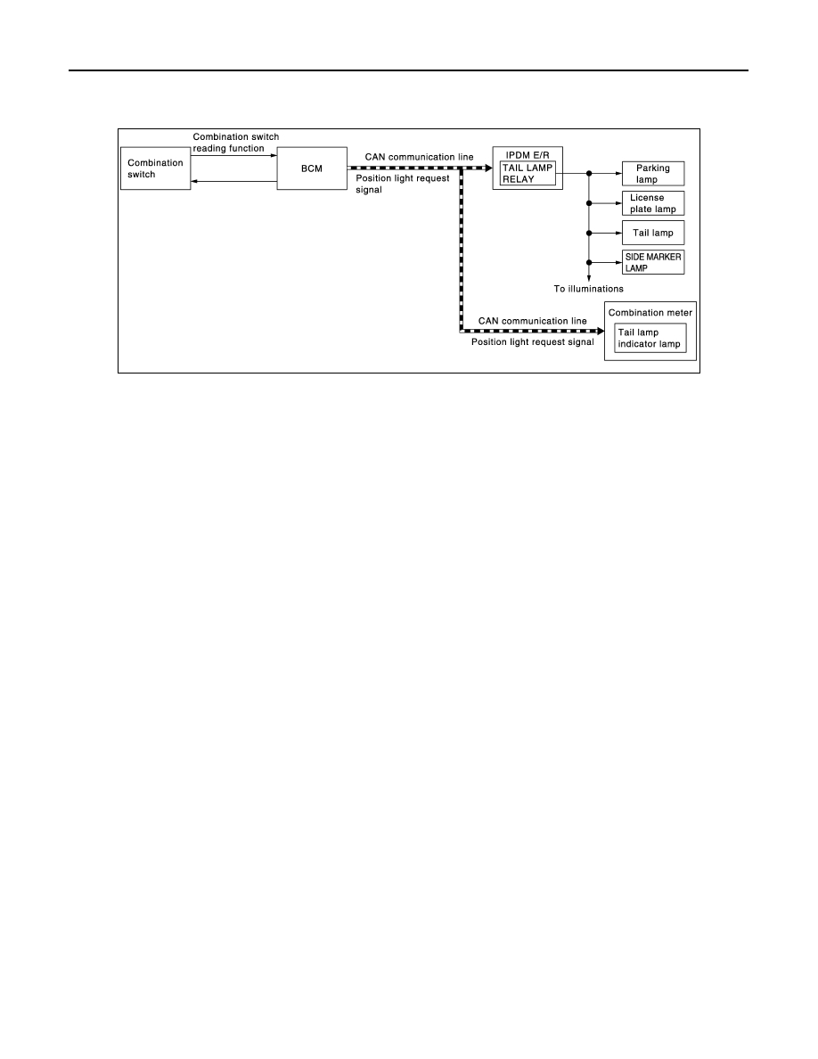
SYSTEM DIAGRAM

OUTLINE

Parking, license plate, side marker and tail lamps are controlled by combination switch reading function and
headlamp control function of BCM, and relay control function of IPDM E/R.

PARKING, LICENSE PLATE, SIDE MARKER AND TAIL LAMPS OPERATION 

• BCM detects the combination switch condition by the combination switch reading function.
• BCM transmits the position light request signal to IPDM E/R and the combination meter via CAN communi-

cation according to the ON/OFF condition of the parking, license plate, side marker and tail lamps.

Parking, license plate, side marker and tail lamps ON condition

- Lighting switch 1ST
- Lighting switch 2ND
- Lighting switch AUTO, and the auto light function ON judgment.
• IPDM E/R turns the integrated tail lamp relay ON and turns the parking, license plate, side marker and tail

lamps ON according to the position light request signal.

• Combination meter turns the tail lamp indicator lamp ON according to the position light request signal.

PARKING, LICENSE PLATE, SIDE MARKER AND TAIL LAMP SYSTEM : Circuit Dia-

JMLIA1349GB

SYSTEM

EXL-137

< SYSTEM DESCRIPTION >

[HALOGEN TYPE]

C

D

E

F

G

H

I

J

K

M

A

B

EXL

N

O

P

gram

INFOID:0000000009653134

PARKING, LICENSE PLATE, SIDE MARKER AND TAIL LAMP SYSTEM : Fail-safe

INFOID:0000000009653135

CAN COMMUNICATION CONTROL

When CAN communication with ECM and BCM is impossible, IPDM E/R performs fail-safe control. After CAN
communication recovers normally, it also returns to normal control.

JMLIA2113GB

EXL-138

< SYSTEM DESCRIPTION >

[HALOGEN TYPE]

SYSTEM

If No CAN Communication Is Available With BCM

FRONT FOG LAMP SYSTEM

FRONT FOG LAMP SYSTEM : System Description

INFOID:0000000009653136

SYSTEM DIAGRAM

OUTLINE

Front fog lamp is controlled by combination switch reading function, front fog lamp control function of BCM,
and relay control function of IPDM E/R.

FRONT FOG LAMP OPERATION 

• BCM detects the combination switch condition by the combination switch reading function.
• BCM transmits the front fog light request signal to IPDM E/R via CAN communication according to the front

fog lamp ON condition.

Front fog lamp ON condition

- Front fog lamp switch ON, and any of the following condition is satisfied. (except for the high beam ON)
• Lighting switch 2ND
• Lighting switch AUTO (auto light function ON judgment)
IPDM E/R turns the integrated front fog lamp relay ON, and turns the front fog lamp ON according to the front
fog light request signal.

Control part

Fail-safe operation

• Parking  lamp
• License plate lamp
• Illumination
• Tail lamp
• Side marker lamp

• Turns ON the tail lamp relay when the ignition switch is turned ON
• Turns OFF the tail lamp relay when the ignition switch is turned OFF

JMLIA1154GB

SYSTEM

EXL-139

< SYSTEM DESCRIPTION >

[HALOGEN TYPE]

C

D

E

F

G

H

I

J

K

M

A

B

EXL

N

O

P

FRONT FOG LAMP SYSTEM : Circuit Diagram

INFOID:0000000009653137

FRONT FOG LAMP SYSTEM : Fail-safe

INFOID:0000000009653138

CAN COMMUNICATION CONTROL

When CAN communication with ECM and BCM is impossible, IPDM E/R performs fail-safe control. After CAN
communication recovers normally, it also returns to normal control.

If No CAN Communication Is Available With BCM

JMLIA2112GB


Content   ..  631  632  633  634   ..