Nissan Quest E52. Manual - part 621


  Index      Nissan     Nissan Quest E52 (2011-2014 year) - Service and Repair Manual


Search            


Content   ..  619  620  621  622   ..


Nissan Quest E52. Manual - part 621


EXL-88

< SYMPTOM DIAGNOSIS >

[XENON TYPE]

EXTERIOR LIGHTING SYSTEM SYMPTOMS

SYMPTOM DIAGNOSIS

EXTERIOR LIGHTING SYSTEM SYMPTOMS

WITHOUT DAYTIME RUNNING LIGHT SYSTEM

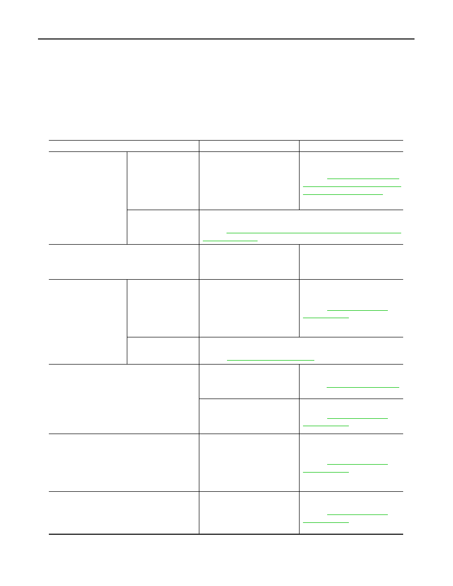
WITHOUT DAYTIME RUNNING LIGHT SYSTEM : Symptom Table

INFOID:0000000009653069

CAUTION:

Perform the self-diagnosis with CONSULT before the symptom diagnosis. Perform the trouble diagno-
sis if any DTC is detected.

Symptom

Possible cause

Inspection item

Headlamp (HI) is not 
turned ON.

One side

• Fuse
• Halogen bulb (HI)
• Harness between IPDM E/R 

and headlamp (HI)

• Harness between headlamp 

(HI) and ground

• IPDM E/R

Headlamp (HI) circuit
Refer to 

EXL-62, "WITHOUT DAY-

TIME RUNNING LIGHT SYSTEM : 
Component Function Check"

.

Both sides

Symptom diagnosis
 “BOTH SIDE HEADLAMPS (HI) ARE NOT TURNED ON”
Refer to 

EXL-94, "WITHOUT DAYTIME RUNNING LIGHT SYSTEM : Di-

agnosis Procedure"

.

High beam indicator lamp is not turned ON.
[Headlamp (HI) is turned ON.]

Combination meter

• Combination meter 

Data monitor “HI-BEAM IND”

• BCM (HEAD LAMP)

Active test “HEADLAMP”

Headlamp (LO) is not 
turned ON.

One side

• Fuse
• Xenon bulb (LO)
• Harness between IPDM E/R 

and headlamp lamp (LO)

• Harness between headlamp 

(LO) and ground

• IPDM E/R

Headlamp (LO) circuit
Refer to 

EXL-66, "Component 

Function Check"

.

Both sides

Symptom diagnosis
“BOTH SIDE HEADLAMPS (LO) ARE NOT TURNED ON”
Refer to 

EXL-96, "Diagnosis Procedure"

.

Each lamp is not turned ON/OFF with lighting switch 
AUTO.

• Combination switch
• Harness between combination 

switch and BCM

• BCM

Combination switch
Refer to 

BCS-96, "Symptom Table"

.

• Optical sensor
• Harness between optical sen-

sor and BCM

• BCM

 Optical sensor
Refer to 

EXL-83, "Component 

Function Check"

.

Parking lamp is not turned ON.

• Fuse
• Parking lamp bulb
• Harness between IPDM E/R 

and front combination lamp

• Harness between front combi-

nation lamp and ground

• IPDM E/R

Parking lamp circuit
Refer to 

EXL-72, "Component 

Function Check"

.

Front side marker lamp is not turned ON.

• Front side marker lamp bulb
• Harness between IPDM E/R 

and front side marker lamp

• Harness between front side 

marker lamp and ground

Front side marker lamp circuit
Refer to 

EXL-74, "Component 

Function Check"

.

EXTERIOR LIGHTING SYSTEM SYMPTOMS

EXL-89

< SYMPTOM DIAGNOSIS >

[XENON TYPE]

C

D

E

F

G

H

I

J

K

M

A

B

EXL

N

O

P

WITH DAYTIME RUNNING LIGHT SYSTEM

Tail lamp (Rear side marker lamp) is not turned ON.

• Fuse
• Tail lamp bulb
• Harness between IPDM E/R 

and rear combination lamp 

• Harness between rear combi-

nation lamp and ground

• IPDM E/R

Tail lamp circuit
Refer to 

EXL-75, "Component 

Function Check"

.

License plate lamp is not turned ON.

• License plate lamp bulb
• Harness between IPDM E/R 

and license plate lamp

• Harness between license plate 

lamp and ground

License plate lamp circuit
Refer to 

EXL-77, "Component 

Function Check"

.

Parking lamp, side marker lamp, tail lamp and li-
cense plate lamp are not turned ON.

Symptom diagnosis
“PARKING, SIDE MARKER, LICENSE PLATE AND TAIL LAMPS ARE 
NOT TURNED ON”
Refer to 

EXL-97, "Diagnosis Procedure"

.

Tail lamp indicator is not turned ON.
(Exterior lamps are turned ON.)

Combination meter

• Combination meter

Data monitor “LIGHT IND”

• BCM (HEADLAMP)

Active test “TAIL LAMP”

Turn signal lamp does not 
blink.

Indicator lamp is nor-
mal.
(Applicable side per-
forms high flasher acti-
vation.)

• Turn signal lamp bulb
• Door mirror
• Harness between BCM and 

each turn signal lamp

• Harness between each turn sig-

nal lamp and ground

Turn signal lamp circuit
Refer to 

EXL-78, "Component 

Function Check"

.

Indicator lamp is includ-
ed.

• Combination switch
• Harness between combination 

switch and BCM

• BCM

Combination switch
Refer to 

BCS-96, "Symptom Table"

.

Turn signal indicator lamp 
does not blink.
(Turn signal lamp is nor-
mal.)

One side

Combination meter

Both sides
(Always)

• Turn signal indicator lamp sig-

nal

• BCM
• Combination meter

• Combination meter 

Data monitor “TURN IND”

• BCM (FLASHER)

Active test “FLASHER”

Both sides
(Only when activating 
hazard warning lamp 
with ignition switch 
OFF)

• Combination meter power sup-

ply and ground circuit

• Combination meter

Combination meter
Power supply and ground circuit
Refer to 

MWI-72, "COMBINATION 

METER : Diagnosis Procedure"

.

• Hazard warning lamp does not activate.
• Hazard warning lamp continues activating.
(Turn signal is normal.)

• Hazard switch
• Harness between hazard 

switch and BCM

• Harness between hazard 

switch and ground

• BCM

Hazard switch circuit
Refer to 

EXL-86, "Component 

Function Check"

.

Front fog lamp is not 
turned ON.

One side

• Front fog lamp bulb
• Harness between IPDM E/R 

and front fog lamp

• Harness between front fog lamp 

and ground

• IPDM E/R

Front fog lamp circuit
Refer to 

EXL-81, "Component 

Function Check"

.

Both sides

Symptom diagnosis
“BOTH SIDE FRONT FOG LAMPS ARE NOT TURNED ON”
Refer to 

EXL-98, "Diagnosis Procedure"

.

Symptom

Possible cause

Inspection item

EXL-90

< SYMPTOM DIAGNOSIS >

[XENON TYPE]

EXTERIOR LIGHTING SYSTEM SYMPTOMS

WITH DAYTIME RUNNING LIGHT SYSTEM : Symptom Table

INFOID:0000000009653070

CAUTION:

Perform the self-diagnosis with CONSULT before the symptom diagnosis. Perform the trouble diagno-
sis if any DTC is detected.

Symptom

Possible cause

Inspection item

Headlamp (HI) is not 
turned ON.

One side

• Fuse
• Halogen bulb (HI)
• Harness between IPDM E/R 

and headlamp (HI)

• Harness between headlamp 

(HI) and ground

• IPDM E/R

Headlamp (HI) circuit
Refer to 

EXL-63, "WITH DAYTIME 

RUNNING LIGHT SYSTEM : Com-
ponent Function Check"

.

• Harness between IPDM E/R 

and daytime running light relay 

• Daytime running light relay 
• IPDM E/R

Daytime running light relay circuit
Refer to 

EXL-68, "Component 

Function Check"

.

Both sides

Symptom diagnosis
 “BOTH SIDE HEADLAMPS (HI) ARE NOT TURNED ON”
Refer to 

EXL-94, "WITH DAYTIME RUNNING LIGHT SYSTEM : Diag-

nosis Procedure"

.

High beam indicator lamp is not turned ON.
[Headlamp (HI) is turned ON.]

Combination meter

• Combination meter 

Data monitor “HI-BEAM IND”

• BCM (HEAD LAMP)

Active test “HEADLAMP”

Headlamp (LO) is not 
turned ON.

One side

• Fuse
• Xenon bulb (LO)
• Harness between IPDM E/R 

and headlamp lamp (LO)

• Harness between headlamp 

(LO) and ground

• IPDM E/R

Headlamp (LO) circuit
Refer to 

EXL-66, "Component 

Function Check"

.

Both sides

Symptom diagnosis
“BOTH SIDE HEADLAMPS (LO) ARE NOT TURNED ON”
Refer to 

EXL-96, "Diagnosis Procedure"

.

Each lamp is not turned ON/OFF with lighting switch 
AUTO.

• Combination switch
• Harness between combination 

switch and BCM

• BCM

Combination switch
Refer to 

BCS-96, "Symptom Table"

.

• Optical sensor
• Harness between optical sen-

sor and BCM

• BCM

 Optical sensor
Refer to 

EXL-83, "Component 

Function Check"

.

Daytime running light is not turned ON.
[Headlamp (HI) is turned ON.]

• Fuse
• Harness between IPDM E/R 

and daytime running light relay 

• Daytime running light relay 
• IPDM E/R
• BCM
• ECM
• Combination meter

• Daytime running light relay circuit

Refer to 

EXL-68, "Component 

Function Check"

.

• BCM (HEADLAMP)

Data monitor “ENGINE STATE”

• Combination meter

Data monitor “PKB SW”

• BCM (HEADLAMP)

Active test “DAYTIME RUNNING 
LIGHT”

Parking lamp is not turned ON.

• Fuse
• Parking lamp bulb
• Harness between IPDM E/R 

and front combination lamp

• IPDM E/R

Parking lamp circuit
Refer to 

EXL-97, "Diagnosis Proce-

dure"

.

EXTERIOR LIGHTING SYSTEM SYMPTOMS

EXL-91

< SYMPTOM DIAGNOSIS >

[XENON TYPE]

C

D

E

F

G

H

I

J

K

M

A

B

EXL

N

O

P

Front side marker lamp is not turned ON.

• Front side marker lamp bulb
• Harness between IPDM E/R 

and front side marker lamp

• Harness between front side 

marker lamp and ground

• IPDM E/R

Front side marker lamp circuit
Refer to 

EXL-74, "Component 

Function Check"

.

Tail lamp (Rear side marker lamp) is not turned ON.

• Fuse
• Tail lamp bulb
• Harness between IPDM E/R 

and rear combination lamp 

• Harness between and rear 

combination lamp and ground

Tail lamp circuit
Refer to 

EXL-75, "Component 

Function Check"

.

License plate lamp is not turned ON.

• License plate lamp bulb
• Harness between IPDM E/R 

and license plate lamp

• Harness between license plate 

lamp and ground

License plate lamp circuit
Refer to 

EXL-77, "Component 

Function Check"

.

Parking lamp, side marker lamp, tail lamp and li-
cense plate lamp are not turned ON.

Symptom diagnosis
“PARKING, SIDE MARKER, LICENSE PLATE AND TAIL LAMPS ARE 
NOT TURNED ON”
Refer to 

EXL-97, "Diagnosis Procedure"

.

Tail lamp indicator is not turned ON.
(Exterior lamps are turned ON.)

Combination meter

• Combination meter

Data monitor “LIGHT IND”

• BCM (HEADLAMP)

Active test “TAIL LAMP”

Turn signal lamp does not 
blink.

Indicator lamp is nor-
mal.
(Applicable side per-
forms high flasher acti-
vation.)

• Turn signal lamp bulb
• Door mirror
• Harness between BCM and 

each turn signal lamp

• Harness between each turn sig-

nal lamp and ground

Turn signal lamp circuit
Refer to 

EXL-78, "Component 

Function Check"

.

Indicator lamp is includ-
ed.

• Combination switch
• Harness between combination 

switch and BCM

• BCM

Combination switch
Refer to 

BCS-96, "Symptom Table"

.

Turn signal indicator lamp 
does not blink.
(Turn signal lamp is nor-
mal.)

One side

Combination meter

Both sides
(Always)

• Turn signal indicator lamp sig-

nal

• BCM
• Combination meter

• Combination meter 

Data monitor “TURN IND”

• BCM (FLASHER)

Active test “FLASHER”

Both sides
(Only when activating 
hazard warning lamp 
with ignition switch 
OFF)

• Combination meter power sup-

ply and ground circuit

• Combination meter

Combination meter
Power supply and ground circuit
Refer to 

MWI-72, "COMBINATION 

METER : Diagnosis Procedure"

.

• Hazard warning lamp does not activate.
• Hazard warning lamp continues activating.
(Turn signal is normal.)

• Hazard switch
• Harness between hazard 

switch and BCM

• Harness between hazard 

switch and ground

• BCM

Hazard switch circuit
Refer to 

EXL-86, "Component 

Function Check"

.

Symptom

Possible cause

Inspection item


Content   ..  619  620  621  622   ..