Nissan Quest E52. Manual - part 604


  Index      Nissan     Nissan Quest E52 (2011-2014 year) - Service and Repair Manual


Search            


Content   ..  602  603  604  605   ..


Nissan Quest E52. Manual - part 604


EXL-20

< SYSTEM DESCRIPTION >

[XENON TYPE]

SYSTEM

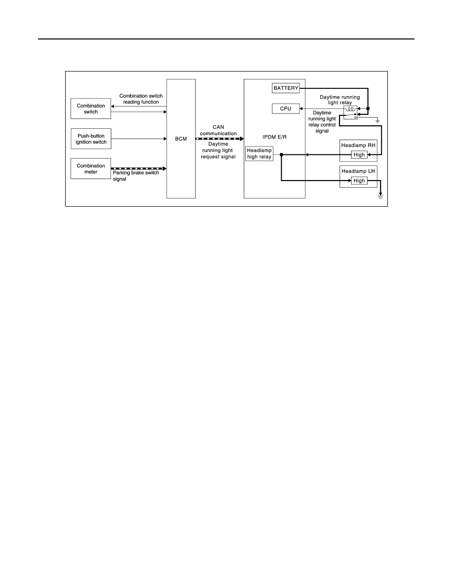
DAYTIME RUNNING LIGHT SYSTEM : System Description

INFOID:0000000009653021

SYSTEM DIAGRAM

OUTLINE

• Turns the headlamp high ON (high beam at approximately half illumination) as the daytime running light.
• Daytime running light is controlled by daytime running light control function and combination switch reading

function of BCM, and relay control function of IPDM E/R.

DAYTIME RUNNING LIGHT OPERATION 

• BCM detects the combination switch condition by the combination switch reading function.
• BCM detects the engine condition according to push-button ignition switch
• BCM detects the parking brake condition by the parking brake switch signal received from combination

meter using CAN communication.

• BCM transmits the daytime running light request signal to IPDM E/R using CAN communication according to

the daytime running light ON condition.

Daytime running light ON condition

- Engine running
- Lighting switch OFF or 1ST
- Lighting switch AUTO, and the auto light function OFF judgment
- Parking brake switch OFF
• IPDM E/R controls the daytime running light relay (ground-side) to turn ON according to the daytime running

light request signal.

• Power is supplied from the daytime running light relay through headlamp high RH and IPDM E/R to head-

lamp high LH. And high beam headlamps are illuminated (approximately half illumination) as the daytime
running light.

JMLIA2127GB

SYSTEM

EXL-21

< SYSTEM DESCRIPTION >

[XENON TYPE]

C

D

E

F

G

H

I

J

K

M

A

B

EXL

N

O

P

DAYTIME RUNNING LIGHT SYSTEM : Circuit Diagram

INFOID:0000000009653022

HEADLAMP AIMING CONTROL (MANUAL)

HEADLAMP AIMING CONTROL (MANUAL) : System Description

INFOID:0000000009653023

The headlamp levelizer adjusts the headlamp light axis upward and downward with the aiming motor inte-
grated in the front combination lamp.

TURN SIGNAL AND HAZARD WARNING LAMP SYSTEM

JMLIA2075GB

EXL-22

< SYSTEM DESCRIPTION >

[XENON TYPE]

SYSTEM

TURN SIGNAL AND HAZARD WARNING LAMP SYSTEM : System Description

INFOID:0000000009653024

SYSTEM DIAGRAM

OUTLINE

Turn signal and the hazard warning lamp is controlled by combination switch reading function, flasher control
function and auto hazard function of BCM.

TURN SIGNAL LAMP OPERATION

• BCM detects the combination switch condition by the combination switch reading function.
• BCM supplies voltage to the right (left) turn signal lamp circuit when the ignition switch is turned ON and the

turn signal switch is in the right (left) position. BCM blinks the turn signal lamp.

HAZARD WARNING LAMP OPERATION

BCM supplies voltage to both turn signal lamp circuit when the hazard switch is turned ON. BCM blinks the
hazard warning lamp.

TURN SIGNAL INDICATOR LAMP AND TURN SIGNAL SOUND OPERATION

• BCM transmits the turn indicator signal to the combination meter via CAN communication while the turn sig-

nal lamp and the hazard warning lamp operating.

• Combination meter outputs the turn signal sound with the integrated buzzer while blinking the turn signal

indicator lamp according to the turn indicator signal.

AUTO HAZARD FUNCTION

• Air bag diagnosis sensor unit transmits air bag signal to BCM, when air bag diagnosis sensor unit detects

strong impact to the vehicle body while ignition switch is ON.

• When air bag signal from air bag diagnosis sensor unit is detected, BCM supplies voltage to each turn signal

lamp system and hazard lamp blinks.

NOTE:
Auto hazard function may not be operated depending on status of collision.

3-TIME FLASHER FUNCTION

• By a short touch of the turn signal lever, BCM blinks the turn signal lamps 3 times in the selected direction.
• Cancels the operation when short touch of the turn signal lever in the reverse direction during the 3-time

flasher function operation.

HIGH FLASHER OPERATION

• BCM detects the turn signal lamp circuit status from the current value.
• BCM increases the turn signal lamp blinking speed if the bulb or harness open is detected with the turn sig-

nal lamp operating.
NOTE:
The blinking speed is normal while operating the hazard warning lamp.

JMLIA0919GB

SYSTEM

EXL-23

< SYSTEM DESCRIPTION >

[XENON TYPE]

C

D

E

F

G

H

I

J

K

M

A

B

EXL

N

O

P

TURN SIGNAL AND HAZARD WARNING LAMP SYSTEM : Circuit Diagram

INFOID:0000000009653025

PARKING, LICENSE PLATE, SIDE MARKER AND TAIL LAMP SYSTEM

PARKING, LICENSE PLATE, SIDE MARKER AND TAIL LAMP SYSTEM : System De-

JMLIA2111GB


Content   ..  602  603  604  605   ..