Nissan Quest E52. Manual - part 590


  Index      Nissan     Nissan Quest E52 (2011-2014 year) - Service and Repair Manual


Search            


Content   ..  588  589  590  591   ..


Nissan Quest E52. Manual - part 590


CYLINDER BLOCK

EM-109

< UNIT DISASSEMBLY AND ASSEMBLY >

[VQ35DE]

C

D

E

F

G

H

I

J

K

L

M

A

EM

N

P

O

b.

Install thrust bearings (1) to the both sides of the No. 3 journal
housing on cylinder block and main bearing cap.

• Install thrust bearings with the oil groove (E) facing crankshaft

arm (outside). 

• Install thrust bearing with a projection on one end on cylinder block, and thrust bearing with a projection

at center on main bearing cap. Align each projection with mating notch.

c.

Install main bearings paying attention to the direction.
• Main bearing with oil hole (B) and groove (C) goes on cylinder

block. The one without them goes on main bearing cap.

• Before installing main bearings, apply engine oil to the bearing

surface (inside). Do not apply engine oil to the back surface,
but thoroughly clean it.

• When installing, align main bearing stopper protrusion to cut-

out of cylinder block and main bearing caps.

• Ensure the oil holes on cylinder block and those on the corresponding bearing are aligned.

5.

Install crankshaft to cylinder block.
• While turning crankshaft by hand, check that it turns smoothly. 

6.

Install main bearing caps.
• Main bearing caps are identified by identification mark cast on

them. For installation, face front mark (E) to front side.

NOTE:
Main bearing cap cannot be replaced as a single part, because it
is machined together with cylinder block.
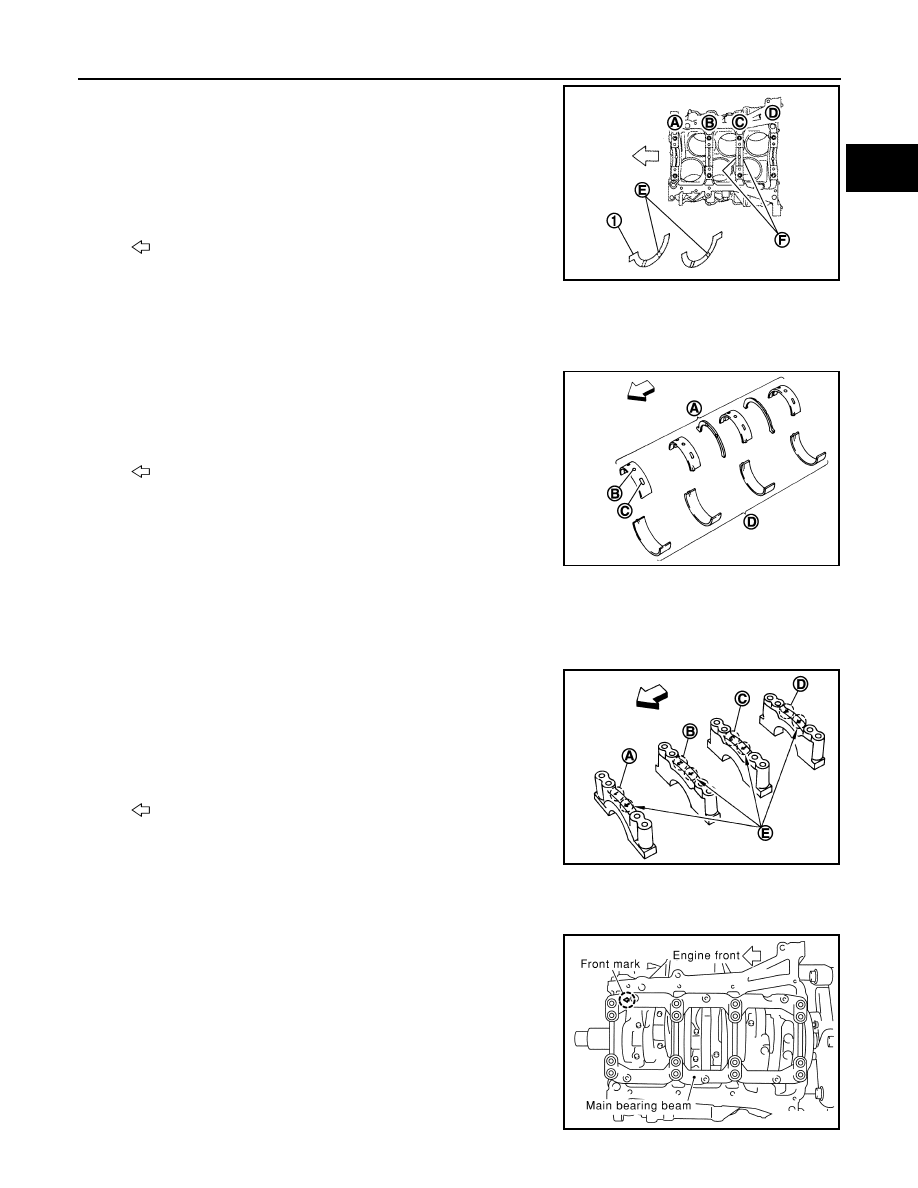
7.

Install main bearing beam.
• Install main bearing beam with front mark facing downward (oil pan side).
• Install main bearing beam with front mark facing front of the

engine.

A

: No. 1

B

: No. 2

C

: No. 3

D

: No. 4

F

: Thrust bearing installation position

: Engine front

JPBIA0199ZZ

A

: Cylinder block side

D

: Main bearing cap side

: Engine front

JPBIA0200ZZ

A

: No. 1

B

: No. 2

C

: No. 3

D

: No. 4

: Engine front

JPBIA0440ZZ

PBIC0881E

EM-110

< UNIT DISASSEMBLY AND ASSEMBLY >

[VQ35DE]

CYLINDER BLOCK

8.

Install main bearing cap bolts in numerical order as shown in the
figure as follows:

a.

Inspect the outer diameter of main bearing cap bolt. Refer to

EM-113, "Inspection"

.

b.

Apply new engine oil to threads and seat surfaces of main bear-
ing cap bolts.

c.

Tighten main bearing cap bolts in several different steps.

d.

Turn all main bearing cap bolts 90 degrees clockwise (angle tightening).

CAUTION:

Use the angle wrench [SST: KV10112100 (BT8653-A)] to
check tightening angle. Never make judgment by visual
inspection. 
• After installing main bearing cap bolts, check that crankshaft

can be rotated smoothly by hand.

• Check the crankshaft end play. Refer to 

EM-113, "Inspection"

.

9.

Install piston to connecting rod as follows:

a.

Using snap ring pliers, install new snap ring to the groove of piston rear side. 
• Insert it fully into groove to install.

b.

Install piston to connecting rod.
• Using an industrial drier or similar tool, heat piston until piston pin can be pushed in by hand without

excess force [approximately 60 to 70

°

C (140 to 158

°

F)]. From the front to the rear, insert piston pin into

piston and connecting rod.

• Assemble so that the front mark on the piston crown and the

cylinder number on connecting rod are positioned as shown in
the figure.

c.

Install new snap ring to the groove of the piston front side. 
• Insert it fully into groove to install.
• After installing, check that connecting rod moves smoothly.

10. Using a piston ring expander (commercial service tool) (A),

install piston rings.

CAUTION:

• When installing piston rings, be careful not to damage

piston.

• Be careful not to damage piston rings by expending them

excessively.

: Engine front

: 35.3 N·m (3.6 kg-m, 26 ft-lb)

JPBIA0439ZZ

PBIC0921E

SEM838F

JPBIA0194ZZ

CYLINDER BLOCK

EM-111

< UNIT DISASSEMBLY AND ASSEMBLY >

[VQ35DE]

C

D

E

F

G

H

I

J

K

L

M

A

EM

N

P

O

• If there is stamped mark on ring, mount it with marked side up.

NOTE:
If there is no stamp on ring, no specific orientation is required
for installation.

• Position each ring with the gap as shown in the figure referring

to the piston front mark (D).

• Check the piston rings side clearance. Refer to 

EM-113, "Inspection"

.

11. Install connecting rod bearings to connecting rod and connecting rod bearing cap.

CAUTION:

Be careful not to drop connecting rod bearing, and to scratch the surface.
• Before installing connecting rod bearings, apply engine oil to the bearing surface (inside). Do not apply

engine oil to the back surface, but thoroughly clean it. 

• When installing, align connecting rod bearing stopper protru-

sion (B) with cutout (C) of connecting rod and connecting rod
bearing cap to install. 

• Ensure the oil hole (A) on connecting rod and that on the cor-

responding bearing are aligned. 

12. Install piston and connecting rod assembly to crankshaft. 

• Position crankshaft pin corresponding to connecting rod to be installed onto the bottom dead center. 
• Apply engine oil sufficiently to the cylinder bore, piston and crankshaft pin journal.
• Match the cylinder position with the cylinder number on connecting rod to install. 
• Be sure that front mark on piston crown is facing front of engine.
• Using a piston ring compressor [SST: EM03470000 (J-8037)]

(A) or suitable tool, install piston with the front mark on the pis-
ton crown facing the front of the engine.

CAUTION:

Be careful not to damage the cylinder wall and crankshaft
pin, resulting from an interference of the connecting rod big
end.

Stamped mark:

Top ring (A)

: —

Second ring (B)

: 2 R

JPBIA0263ZZ

C

: Top ring gap

E

: Oil ring upper or lower rail gap (either of then)

F

: Second ring and oil ring spacer gap

a

: 90 degrees

b

: 45 degrees

JPBIA0205ZZ

JPBIA0206ZZ

JPBIA0207ZZ

EM-112

< UNIT DISASSEMBLY AND ASSEMBLY >

[VQ35DE]

CYLINDER BLOCK

13. Install connecting rod bearing cap.

• Match the stamped cylinder number marks on connecting rod

with those on connecting rod bearing cap to install.

• Be sure that front mark (H) on connecting rod bearing cap is facing front of the engine.

14. Tighten connecting rod bolt as follows:
a.

Inspect the outer diameter of connecting rod bolt. Refer to 

EM-113, "Inspection"

.

b.

Apply engine oil to the threads and seats of connecting rod bolts. 

c.

Tighten connecting rod bolts.

d.

Then tighten all connecting rod bolts 90 degrees clockwise (angle tightening).

CAUTION:

Always use the angle wrench [SST: KV10112100 (BT8653-
A)]. Avoid tightening based on visual check alone.
• After tightening connecting rod bolts, check that crankshaft

rotates smoothly.

• Check the connecting rod side clearance. Refer to 

EM-113,

"Inspection"

.

15. Install baffle plate to main bearing beam.

16. Install new rear oil seal retainer to cylinder block. Refer to 

EM-45, "REAR OIL SEAL : Removal and Instal-

lation"

.

17. Install pilot converter.

• With drift [outer diameter: approximately 33 mm (1.30 in)],

press-fit as far as it will go.

A

: Sample codes

B

: Bearing stopper groove

C

: Small-end diameter grade

D

: Standard stamp

E

: Weight grade

F

: Cylinder No.

G

: Management code

I

: Management code

JPBIA0208ZZ

: 19.6 N·m (2.0 kg-m, 14 ft-lb)

SEM953E

PBIC0899E


Content   ..  588  589  590  591   ..