Nissan Quest E52. Manual - part 581


  Index      Nissan     Nissan Quest E52 (2011-2014 year) - Service and Repair Manual


Search            


Content   ..  579  580  581  582   ..


Nissan Quest E52. Manual - part 581


TIMING CHAIN

EM-73

< UNIT DISASSEMBLY AND ASSEMBLY >

[VQ35DE]

C

D

E

F

G

H

I

J

K

L

M

A

EM

N

P

O

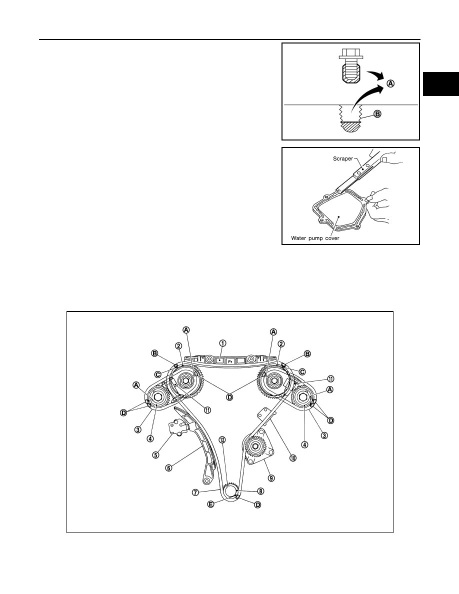
• Remove old liquid gasket from bolt hole (B) and thread.

21. Use a scraper to remove all traces of old liquid gasket from

water pump cover.

INSTALLATION

CAUTION:

Do not reuse O-rings.
NOTE:
The below figure shows the relationship between the mating mark on each timing chain and that on the corre-
sponding sprocket, with the components installed.

A

: Remove sticking old liquid gasket 

JPBIA0051ZZ

SEM926E

1.

Internal chain guide

2.

Camshaft sprocket (INT)

3.

Timing chain (secondary)

4.

Camshaft sprocket (EXH)

5.

Timing chain tensioner (primary)

6.

Slack guide

7.

Timing chain (primary)

8.

Crankshaft sprocket

9.

Water pump

JPBIA1716GB

EM-74

< UNIT DISASSEMBLY AND ASSEMBLY >

[VQ35DE]

TIMING CHAIN

1.

Install timing chain tensioners (secondary) to cylinder head as follows if removed.
• Install timing chain tensioners (secondary) with a stopper pin attached and new O-ring.

2.

Install No.1 camshaft bracket. Refer to 

EM-85, "Removal and Installation"

.

3.

Measure difference in levels between front end faces of cam-
shaft bracket (No. 1) and cylinder head. 

• Measure two positions (both intake and exhaust side) for a

single bank.

• If the measured value is out of the standard, reinstall camshaft

bracket (No. 1).

4.

Install rear timing chain case as follows:
• Install new O-rings (1) onto cylinder block.

CAUTION:

Do not reuse O-rings.

a.

Apply liquid gasket with the tube presser (commercial service tool) to rear timing chain case back side as
shown in the figure.
Use Genuine RTV Silicone Sealant or equivalent. Refer to 

GI-22, "Recommended Chemical Prod-

ucts and Sealants"

.

CAUTION:

• For “A” in the figure, completely wipe out liquid gasket extended on a portion touching at engine

coolant.

10. Tension guide

11.

Timing chain tensioner (secondary)

12. Crankshaft key

A.

Mating mark

B.

Mating mark (pink link)

C.

Mating mark (punched)

D.

Mating mark (orange)

E.

Mating mark (notched)

Standard

0.14 to 0.14 mm (

0.0055 to 0.0055 in) 

EMQ0044D

: Engine front

JPBIA0090ZZ

TIMING CHAIN

EM-75

< UNIT DISASSEMBLY AND ASSEMBLY >

[VQ35DE]

C

D

E

F

G

H

I

J

K

L

M

A

EM

N

P

O

• Apply liquid gasket on installation position of water pump and cylinder head very completely.

b.

Align rear timing chain case with dowel pins (bank 1 and bank 2) on cylinder block and install rear timing
chain case.
• Check O-rings stay in place during installation to cylinder block and cylinder head.

c.

Tighten mounting bolts in numerical order as shown in the fig-
ure.
• There are two types of mounting bolts. Refer to the following

for locating bolts.

d.

After all bolts tightening, retighten them to the specified in numerical order as shown in the figure.
• If liquid gasket protrudes, wipe it off immediately.

e.

After installing rear timing chain case (1), check the surface
height difference between the following parts on the oil pan
(upper) mounting surface.

• If not within the standard, repeat the installation procedure.

Bolt length:

Bolt position

20 mm (0.79 in)

: 1, 2, 3, 6, 7, 8, 9, 10

16 mm (0.63 in)

: Except the above

: 12.7 N·m (1.3 kg-m, 9 ft-lb)

PBIC2680E

JPBIA1641ZZ

2

: Cylinder block

Standard

Rear timing chain case to cylinder block:

0.24 to 0.14 mm (

0.009 to 0.006 in)

JPBIA1944ZZ

EM-76

< UNIT DISASSEMBLY AND ASSEMBLY >

[VQ35DE]

TIMING CHAIN

5.

Install water pump. Refer to 

CO-19, "Removal and Installation"

.

6.

Install oil pump. Refer to 

LU-14, "Removal and Installation"

.

7.

Check that dowel pin (A) and crankshaft key (1) are located as
shown in the figure. (No. 1 cylinder at compression TDC)
NOTE:
Though camshaft does not stop at the position as shown in the
figure, for the placement of cam nose, it is generally accepted
camshaft is placed for the same direction of the figure.

CAUTION:

Hole on small dia. side must be used for intake side dowel pin hole. Never misidentify (ignore big
dia. side).

8.

Install timing chain (secondary) and camshaft sprockets (INT and EXH) as follows:

CAUTION:

Mating marks between timing chain and sprockets slip easily. Confirm all mating mark positions
repeatedly during the installation process.

a.

Push plunger of timing chain tensioner (secondary) and keep it
pressed in with stopper pin (A).

b.

Install timing chain (secondary) (1) and camshaft sprockets (INT
and EXH).

NOTE:
Figure shows bank 1 (rear view).
• Align the mating marks on timing chain (secondary) (orange

link) with the ones on camshaft sprockets (INT and EXH)
(punched), and install them.
NOTE:
• Mating marks for camshaft sprocket (INT) are on the back

side of camshaft sprocket (secondary).

• There are two types of mating mark, circle and oval types.

They should be used for the bank 1 and bank 2, respectively.

Camshaft dowel pin

: At cylinder head upper face side in each bank

Crankshaft key

: At cylinder head side of bank 1

JPBIA0094ZZ

JPBIA0095ZZ

A

: Camshaft sprocket (INT) back face

B

: Orange link

C

: Mating mark (Circle)

D

: Camshaft sprocket (EXH) back face

E

: Mating mark (2 circle on front face)

F

: Dowel pin groove

G

: Mating mark (2 ovals on front face)

H

: Mating mark (Oval)

I

: Dowel pin hole

JPBIA1726ZZ


Content   ..  579  580  581  582   ..