Nissan Quest E52. Manual - part 551
EC-414
< DTC/CIRCUIT DIAGNOSIS >
[VQ35DE]
ASCD BRAKE SWITCH
ASCD BRAKE SWITCH
Component Function Check
INFOID:0000000009651271
1.
CHECK ASCD BRAKE SWITCH FUNCTION
With CONSULT
1.
Turn ignition switch ON.
2.
Select “BRAKE SW1” in “DATA MONITOR” mode with CONSULT.
3.
Check “BRAKE SW1” indication under the following conditions.
Without CONSULT
1.
Turn ignition switch ON.
2.
Check the voltage between ECM harness connector terminals.
Is the inspection result normal?
YES
>> INSPECTION END
NO
>> Proceed to
.
Diagnosis Procedure
INFOID:0000000009651272
1.
CHECK ASCD BRAKE SWITCH POWER SUPPLY CIRCUIT
1.
Turn ignition switch OFF.
2.
Disconnect ASCD brake switch harness connector.
3.
Turn ignition switch ON.
4.
Check the voltage between ASCD brake switch harness connector and ground.
Is the inspection result normal?
YES
>> GO TO 3.
NO
>> GO TO 2.
2.
CHECK ASCD BRAKE SWITCH POWER SUPPLY CIRCUIT
1.
Turn ignition switch OFF.
2.
Disconnect fuse block (J/B) harness connector.
3.
Check the continuity between ASCD brake switch harness connector and fuse block (J/B) harness con-
nector.
Is the inspection result normal?
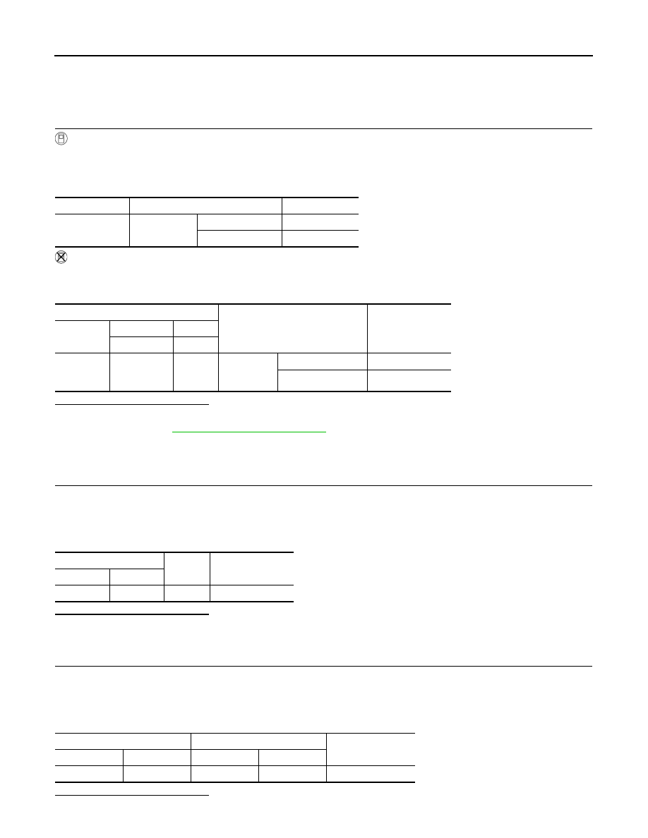
Monitor item
Condition
Indication
BRAKE SW1
Brake pedal
Slightly depressed
OFF
Fully released
ON
ECM
Condition
Voltage
Connector
+
–
Terminal
Terminal
E16
126
(ASCD brake
switch signal)
128
Brake pedal
Slightly depressed
Approx. 0 V
Fully released
Battery voltage
ASCD brake switch
Ground
Voltage
Connector
Terminal
E109
1
Ground
Battery voltage
ASCD brake switch
Fuse block (J/B)
Continuity
Connector
Terminal
Connector
Terminal
E109
1
E103
4F
Existed