Nissan Quest E52. Manual - part 528
 

  Index      Nissan     Nissan Quest E52 (2011-2014 year) - Service and Repair Manual


Search            


Content   ..  526  527  528  529   ..


Nissan Quest E52. Manual - part 528


EC-322

< DTC/CIRCUIT DIAGNOSIS >

[VQ35DE]

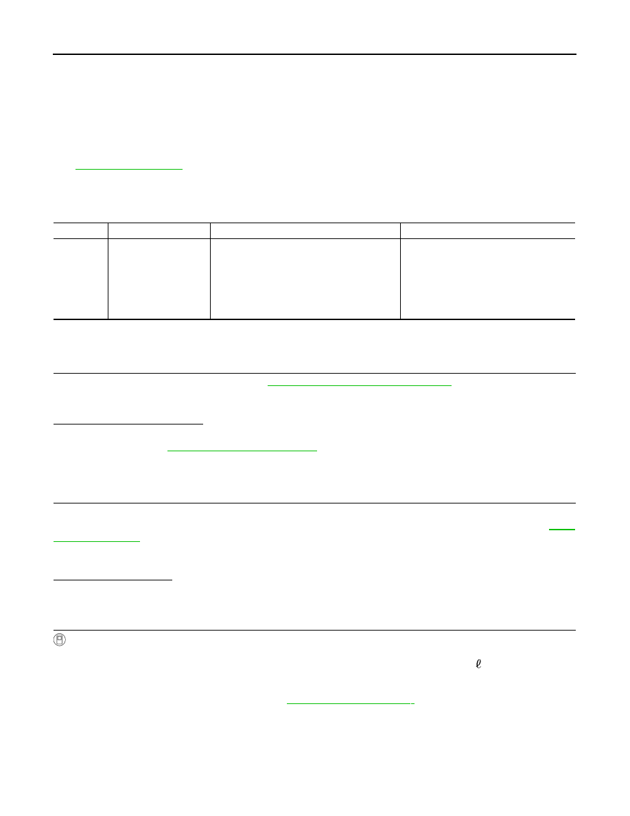
P0461 FUEL LEVEL SENSOR

P0461 FUEL LEVEL SENSOR

DTC Logic

INFOID:0000000009651151

DTC DETECTION LOGIC

NOTE:
• If DTC P0461 is displayed with DTC UXXXX, first perform the trouble diagnosis for DTC UXXXX.
• If DTC P0461 is displayed with DTC P0607, first perform the trouble diagnosis for DTC P0607. Refer

to 

EC-336, "DTC Logic"

.

Driving long distances naturally affect fuel gauge level.
This diagnosis detects the fuel gauge malfunction of the gauge not moving even after a long distance has
been driven.

DTC CONFIRMATION PROCEDURE

1.

PERFORM COMPONENT FUNCTION CHECK

Perform component function check. Refer to 

EC-322, "Component Function Check"

.

Use component function check to check the overall function of the fuel level sensor. During this check, a 1st
trip DTC might not be confirmed.

Is the inspection result normal?

YES

>> INSPECTION END

NO

>> Proceed to 

EC-323, "Diagnosis Procedure"

.

Component Function Check

INFOID:0000000009651152

1.

PRECONDITIONING

WARNING:

When performing the following procedure, always observe the handling of the fuel. Refer to 

FL-5,

"Exploded View"

.

TESTING CONDITION:
Before starting component function check, preparation of draining fuel and refilling fuel is required.

Will CONSULT be used?

YES

>> GO TO 2.

NO

>> GO TO 3.

2.

PERFORM COMPONENT FUNCTION CHECK

With CONSULT

NOTE:
Start from step 10, if it is possible to confirm that the fuel cannot be drained by 30   (7-7/8 US gal, 6-5/
8 Imp gal) in advance.
1.

Prepare a fuel container and a spare hose.

2.

Release fuel pressure from fuel line, refer to 

EC-457, "Work Procedure"

.

3.

Remove the fuel feed hose on the fuel level sensor unit.

4.

Connect a spare fuel hose where the fuel feed hose was removed.

5.

Turn ignition switch OFF and wait at least 10 seconds then turn ON.

6.

Select “FUEL LEVEL SE” in “DATA MONITOR” mode with CONSULT.

7.

Check “FUEL LEVEL SE” output voltage and note it.

8.

Select “FUEL PUMP RELAY” in “ACTIVE TEST” mode with CONSULT.

DTC No.

Trouble diagnosis name

DTC detecting condition

Possible cause

P0461

Fuel level sensor circuit 
range/performance

The output signal of the fuel level sensor does 
not change within the specified range even 
though the vehicle has been driven a long dis-
tance.

• Harness or connectors

(The CAN communication line is open or 
shorted)

• Harness or connectors

(The sensor circuit is open or shorted)

• Combination meter
• Fuel level sensor

P0461 FUEL LEVEL SENSOR

EC-323

< DTC/CIRCUIT DIAGNOSIS >

[VQ35DE]

C

D

E

F

G

H

I

J

K

L

M

A

EC

N

P

O

9.

Touch “ON” and drain fuel approximately 30   (7-7/8 US gal, 6-5/8 Imp gal) and stop it.

10. Check “FUEL LEVEL SE” output voltage and note it.
11. Fill fuel into the fuel tank for 30   (7-7/8 US gal, 6-5/8 Imp gal).
12. Check “FUEL LEVEL SE” output voltage and note it.
13. Confirm whether the voltage changes more than 0.03 V during step 7 to 10 and 10 to 12.
Is the inspection result normal?

YES

>> INSPECTION END

NO

>> Proceed to 

EC-323, "Diagnosis Procedure"

.

3.

PERFORM COMPONENT FUNCTION CHECK

Without CONSULT

NOTE:
Start from step 8, if it is possible to confirm that the fuel cannot be drained by 30   (7-7/8 US gal, 6-5/8
Imp gal) in advance.
1.

Prepare a fuel container and a spare hose.

2.

Release fuel pressure from fuel line. Refer to 

EC-457, "Work Procedure"

.

3.

Remove the fuel feed hose on the fuel level sensor unit. Refer to 

FL-5, "Exploded View"

.

4.

Connect a spare fuel hose where the fuel feed hose was removed.

5.

Turn ignition switch ON.

6.

Drain fuel by 30   (7-7/8 US gal, 6-5/8 Imp gal) from the fuel tank using proper equipment.

7.

Confirm that the fuel gauge indication varies.

8.

Fill fuel into the fuel tank for 30   (7-7/8 US gal, 6-5/8 Imp gal).

9.

Confirm that the fuel gauge indication varies.

Is the inspection result normal?

YES

>> INSPECTION END

NO

>> Proceed to 

EC-323, "Diagnosis Procedure"

.

Diagnosis Procedure

INFOID:0000000009651153

1.

CHECK COMBINATION METER FUNCTION

Check combination meter function. Refer to 

MWI-35, "CONSULT Function"

.

Is the inspection result normal?

YES

>> Check intermittent incident. Refer to 

GI-42, "Intermittent Incident"

.

NO

>> Proceed to 

MWI-77, "Diagnosis Procedure"

.

EC-324

< DTC/CIRCUIT DIAGNOSIS >

[VQ35DE]

P0462, P0463 FUEL LEVEL SENSOR

P0462, P0463 FUEL LEVEL SENSOR

DTC Logic

INFOID:0000000009651154

DTC DETECTION LOGIC

NOTE:
• If DTC P0462 or P0463 is displayed with DTC UXXXX, first perform the trouble diagnosis for DTC

UXXXX.

• If DTC P0462 or P0463 is displayed with DTC P0607, first perform the trouble diagnosis for DTC

P0607.Refer to 

EC-336, "DTC Logic"

.

DTC CONFIRMATION PROCEDURE

1.

PRECONDITIONING

If DTC Confirmation Procedure has been previously conducted, always perform the following before conduct-
ing the next test.
1.

Turn ignition switch OFF and wait at least 10 seconds.

2.

Turn ignition switch ON.

3.

Turn ignition switch OFF and wait at least 10 seconds.

TESTING CONDITION:
Before performing the following procedure, confirm that battery voltage is more than 11 V at ignition
switch ON.

>> GO TO 2.

2.

PERFORM DTC CONFIRMATION PROCEDURE

1.

Turn ignition switch ON and wait at least 5 seconds.

2.

Check 1st trip DTC.

Is 1st trip DTC detected?

YES

>> Proceed to 

EC-324, "Diagnosis Procedure"

.

NO

>> INSPECTION END

Diagnosis Procedure

INFOID:0000000009651155

1.

CHECK COMBINATION METER FUNCTION

Check combination meter function. Refer to 

MWI-35, "CONSULT Function"

.

Is the inspection result normal?

YES

>> Check intermittent incident. Refer to 

GI-42, "Intermittent Incident"

.

NO

>> Proceed to 

MWI-77, "Diagnosis Procedure"

.

DTC No.

Trouble diagnosis name

DTC detecting condition

Possible cause

P0462

Fuel level sensor circuit 
low input

An excessively low voltage from the sensor is 
sent to ECM.

• Harness or connectors

(The CAN communication line is open or 
shorted)

• Harness or connectors

(The sensor circuit is open or shorted)

• Combination meter
• Fuel level sensor

P0463

Fuel level sensor circuit 
high input

An excessively high voltage from the sensor is 
sent to ECM.

P0500 VSS

EC-325

< DTC/CIRCUIT DIAGNOSIS >

[VQ35DE]

C

D

E

F

G

H

I

J

K

L

M

A

EC

N

P

O

P0500 VSS

Description

INFOID:0000000009651156

ECM receives vehicle speed signals from two different paths via CAN communication line: One is from the
ABS actuator and electric unit (control unit) via the combination unit and the other is from TCM.

DTC Logic

INFOID:0000000009651157

DTC DETECTION LOGIC

NOTE:
• If DTC P0500 is displayed with DTC UXXXX, first perform the trouble diagnosis for DTC UXXXX.
• If DTC P0500 is displayed with DTC P0607, first perform the trouble diagnosis for DTC P0607. Refer to 

EC-

336, "DTC Logic"

.

DTC CONFIRMATION PROCEDURE

1.

PRECONDITIONING

If DTC CONFIRMATION PROCEDURE has been previously conducted, always perform the following proce-
dure before conducting the next test.
1.

Turn ignition switch OFF and wait at least 10 seconds.

2.

Turn ignition switch ON.

3.

Turn ignition switch OFF and wait at least 10 seconds.

TESTING CONDITION:
Before performing the following procedure, confirm that battery voltage is 10 V or more at idle.

>> GO TO 2.

2.

PERFORM DTC CONFIRMATION PROCEDURE

1.

Start engine.

2.

Shift the selector lever to D range and wait at least for 2 seconds.

3.

Drive the vehicle at least 5 seconds at 20 km/h (13 MPH) or more.

CAUTION:

Always drive vehicle at a safe speed.
NOTE:
This procedure may be conducted with the drive wheels lifted in the shop or by driving the vehicle. If a
road test is expected to be easier, it is unnecessary to lift the vehicle.

4.

Check 1st trip DTC.

Is 1st trip DTC detected?

YES

>> Proceed to 

EC-325, "Diagnosis Procedure"

NO

>> INSPECTION END

Diagnosis Procedure

INFOID:0000000009651158

1.

CHECK DTC WITH TCM

Check DTC with TCM. Refer to 

TM-35, "CONSULT Function"

.

Is the inspection result normal?

YES

>> GO TO 2.

DTC No.

Trouble diagnosis

(Trouble diagnosis content)

DTC detecting condition

Possible cause

P0500

VEH SPEED SEN/CIRC
(Vehicle speed sensor)

At 20 km/h (13 MPH), ECM detects the fol-
lowing status continuously for 5 seconds or 
more: The difference between a vehicle 
speed calculated by a secondary speed sen-
sor transmitted from TCM to ECM via CAN 
communication and the vehicle speed indi-
cated on the combination meter exceeds 
15km/h (10 MPH).

• Harness or connector

(The CAN communication line is open 
or shorted.) 

• Combination meter
• ABS actuator and electric unit (control 

unit)

• Wheel sensor
• TCM
• Secondary speed sensor


Content   ..  526  527  528  529   ..