Nissan Quest E52. Manual - part 514
EC-266
< DTC/CIRCUIT DIAGNOSIS >
[VQ35DE]
P0300, P0301, P0302, P0303, P0304, P0305, P0306 MISFIRE
3.
Crank engine for approximately 3 seconds, and recheck whether spark is generated between the spark
plug and the grounded metal portion.
Is the inspection result normal?
YES
>> GO TO 7.
NO
>> Check ignition coil, power transistor and their circuits. Refer to
.
7.
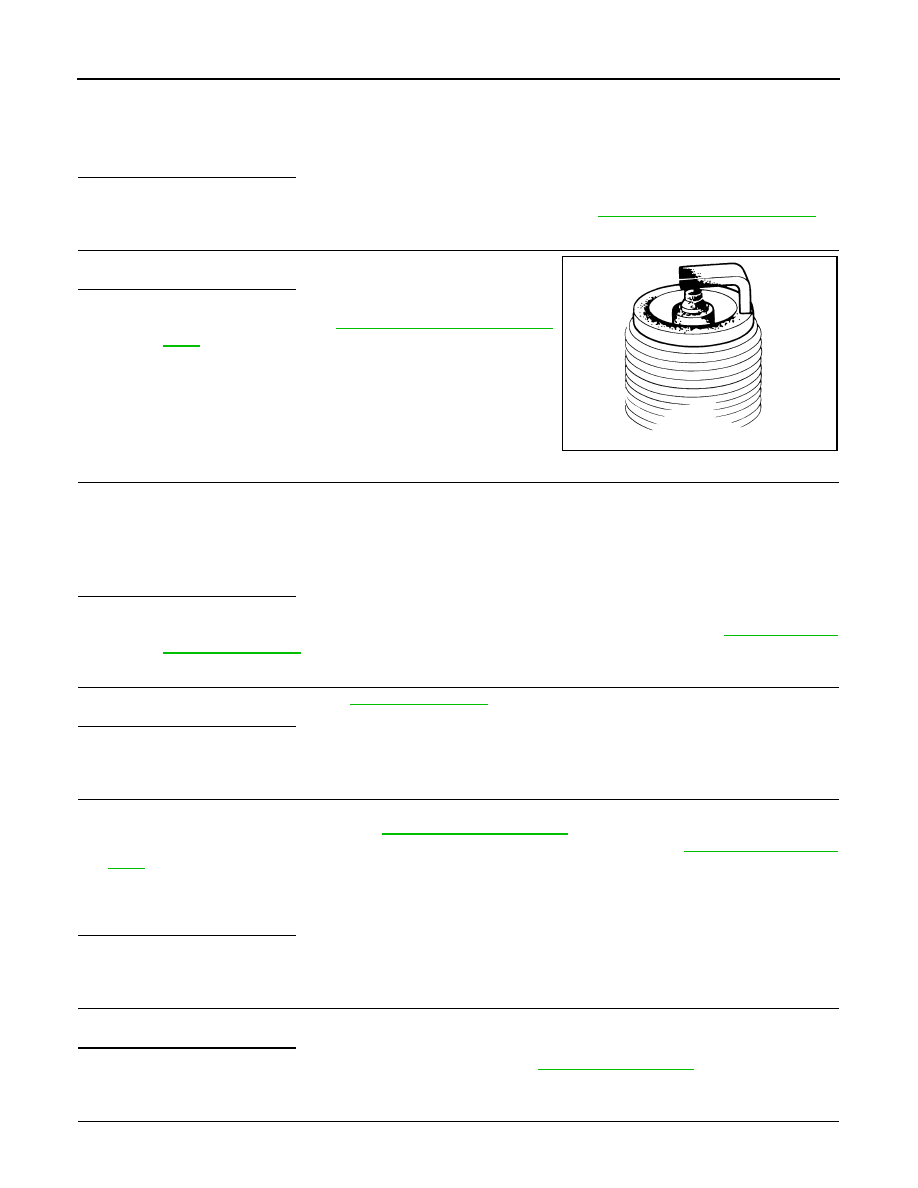
CHECK SPARK PLUG
Check the initial spark plug for fouling, etc.
Is the inspection result normal?
YES
>> Replace spark plug(s) with standard type one(s). For
spark plug type, refer to
.
NO
>> Repair or clean spark plug. Then GO TO 8.
8.
CHECK FUNCTION OF IGNITION COIL-III
1.
Reconnect the initial spark plugs.
2.
Crank engine for approximately 3 seconds, and recheck whether spark is generated between the spark
plug and the grounded portion.
Is the inspection result normal?
YES
>> INSPECTION END
NO
>> Replace spark plug(s) with standard type one(s). For spark plug type, refer to
9.
CHECK COMPRESSION PRESSURE
Check compression pressure. Refer to
.
Is the inspection result normal?
YES
>> GO TO 10.
NO
>> Check pistons, piston rings, valves, valve seats and cylinder head gaskets.
10.
CHECK FUEL PRESSURE
1.
Install all removed parts.
2.
Release fuel pressure to zero. Refer to
.
3.
Install fuel pressure gauge kit [SST: — (J-44321)] and check fuel pressure. Refer to
Is the inspection result normal?
YES
>> GO TO 12.
NO
>> GO TO 11.
11.
DETECT MALFUNCTIONING PART
Check fuel hoses and fuel tubes for clogging.
Is the inspection result normal?
YES
>> Replace “fuel filter and fuel pump assembly”. Refer to
.
NO
>> Repair or replace malfunctioning part.
12.
CHECK IGNITION TIMING
Check idle speed and ignition timing.
Spark should be generated.
SEF156I
Spark should be generated.
At idle: Approximately 350 kPa (3.57 kg/cm
2
, 51 psi)