Nissan Quest E52. Manual - part 500
EC-210
< DTC/CIRCUIT DIAGNOSIS >
[VQ35DE]
P0131, P0151 A/F SENSOR 1
P0131, P0151 A/F SENSOR 1
DTC Logic
INFOID:0000000009651069
DTC DETECTION LOGIC
To judge the malfunction, the diagnosis checks that the A/F signal computed by ECM from the A/F sensor 1
signal is not inordinately low.
DTC CONFIRMATION PROCEDURE
1.
PRECONDITIONING
If DTC Confirmation Procedure has been previously conducted, always perform the following before conduct-
ing the next test.
1.
Turn ignition switch OFF and wait at least 10 seconds.
2.
Turn ignition switch ON.
3.
Turn ignition switch OFF and wait at least 10 seconds.
TESTING CONDITION:
Before performing the following procedure, confirm that battery voltage is more than 10.5 V at idle.
>> GO TO 2.
2.
CHECK A/F SENSOR 1 FUNCTION
With CONSULT
1.
Start engine and warm it up to normal operating temperature.
2.
Select “A/F SEN1 (B1)” or “A/F SEN1 (B2)” in “DATA MONITOR” mode with CONSULT.
3.
Check “A/F SEN1 (B1)” or “A/F SEN1 (B2)” indication.
With GST
Follow the procedure “With CONSULT” above.
Is the indication constantly approx. 0 V?
YES
>> Proceed to
.
NO
>> GO TO 3.
3.
PERFORM DTC CONFIRMATION PROCEDURE
With CONSULT
1.
Turn ignition switch OFF, wait at least 10 seconds.
2.
Turn ignition switch ON.
3.
Turn ignition switch OFF, wait at least 10 seconds and then restart engine.
4.
Drive and accelerate vehicle to more than 40 km/h (25 MPH) within 20 seconds after restarting engine.
CAUTION:
Always drive vehicle at a safe speed.
5.
Maintain the following conditions for approximately 20 consecutive seconds.
NOTE:
• Keep the accelerator pedal as steady as possible during cruising.
• If this procedure is not completed within 1 minute after restarting engine at step 1, return to step
1.
6.
Check 1st trip DTC.
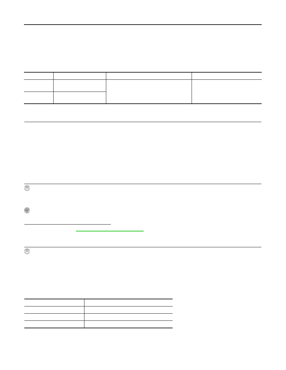
DTC No.
Trouble diagnosis name
DTC detecting condition
Possible cause
P0131
Air fuel ratio (A/F) sensor 1
(bank 1) circuit low voltage
• The A/F signal computed by ECM from the A/
F sensor 1 signal is constantly approx. 0 V.
• Harness or connectors
(The A/F sensor 1 circuit is open or
shorted.)
• A/F sensor 1
P0151
Air fuel ratio (A/F) sensor 1
(bank 2) circuit low voltage
ENG SPEED
1,000 - 3,200 rpm
VHCL SPEED SE
More than 40 km/h (25 mph)
B/FUEL SCHDL
1.5 - 9.0 msec
Selector lever
Suitable position