Nissan Quest E52. Manual - part 400
DLK-314
< DTC/CIRCUIT DIAGNOSIS >
ENCODER
Is the inspection result normal?
YES
>> GO TO 4.
NO
>> Repair or replace harness.
4.
CHECK ENCODER GROUND CIRCUIT
1.
Check continuity between sliding door control unit RH harness connector and automatic sliding door unit
RH harness connector.
2.
Check continuity between sliding door control unit RH harness connector and ground.
Is the inspection result normal?
YES
>> GO TO 5.
NO
>> Repair or replace harness.
5.
CHECK ENCODER CIRCUIT 3
1.
Connect sliding door control unit RH connector and automatic sliding door unit RH connector.
2.
Check voltage between sliding door control unit RH harness connector and ground.
Is the inspection result normal?
YES
>> Replace automatic sliding door unit RH.
NO
>> Replace sliding door control unit RH. Refer to
DLK-500, "RH : Removal and Installation"
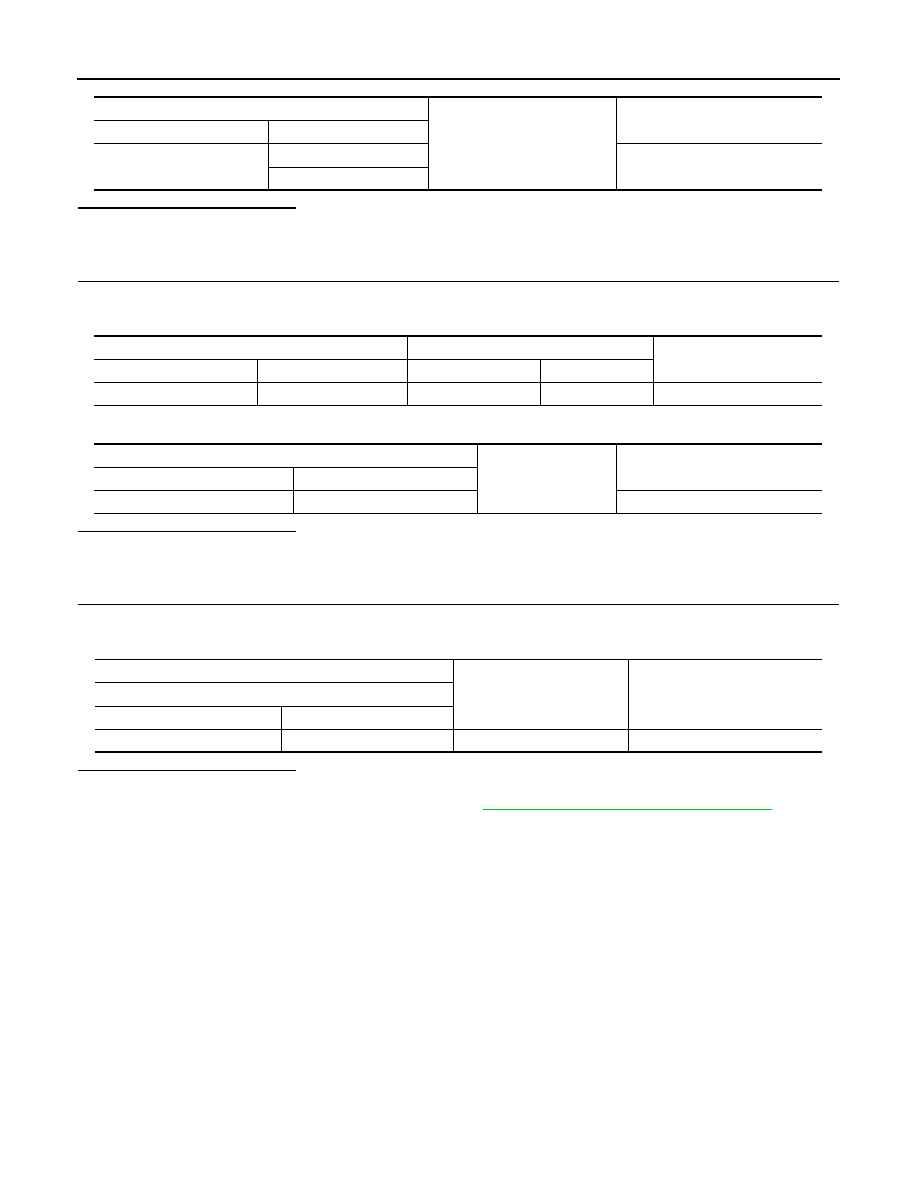
Sliding door control unit RH
Ground
Continuity
Connector
Terminal
B247
4
Not existed
21
Sliding door control unit RH
Automatic sliding door unit RH
Continuity
Connector
Terminal
Connector
Terminal
B247
26
B244
8
Existed
Sliding door control unit RH
Ground
Continuity
Connector
Terminal
B247
26
Not existed
(+)
(
−
)
Voltage
Sliding door control unit RH
Connector
Terminal
B247
26
Ground
0 V