Nissan Quest E52. Manual - part 392
DLK-282
< DTC/CIRCUIT DIAGNOSIS >
AUTOMATIC BACK DOOR CLOSE SWITCH
Is the inspection result normal?
YES
>> GO TO 4.
NO
>> Repair or replace harness.
4.
CHECK AUTOMATIC BACK DOOR CLOSE SWITCH
DLK-282, "Component Inspection"
.
Is the inspection result normal?
YES
>> GO TO 5.
NO
>> Replace automatic back door close switch.
5.
CHECK INTERMITTENT INCIDENT
GI-42, "Intermittent Incident"
>> INSPECTION END
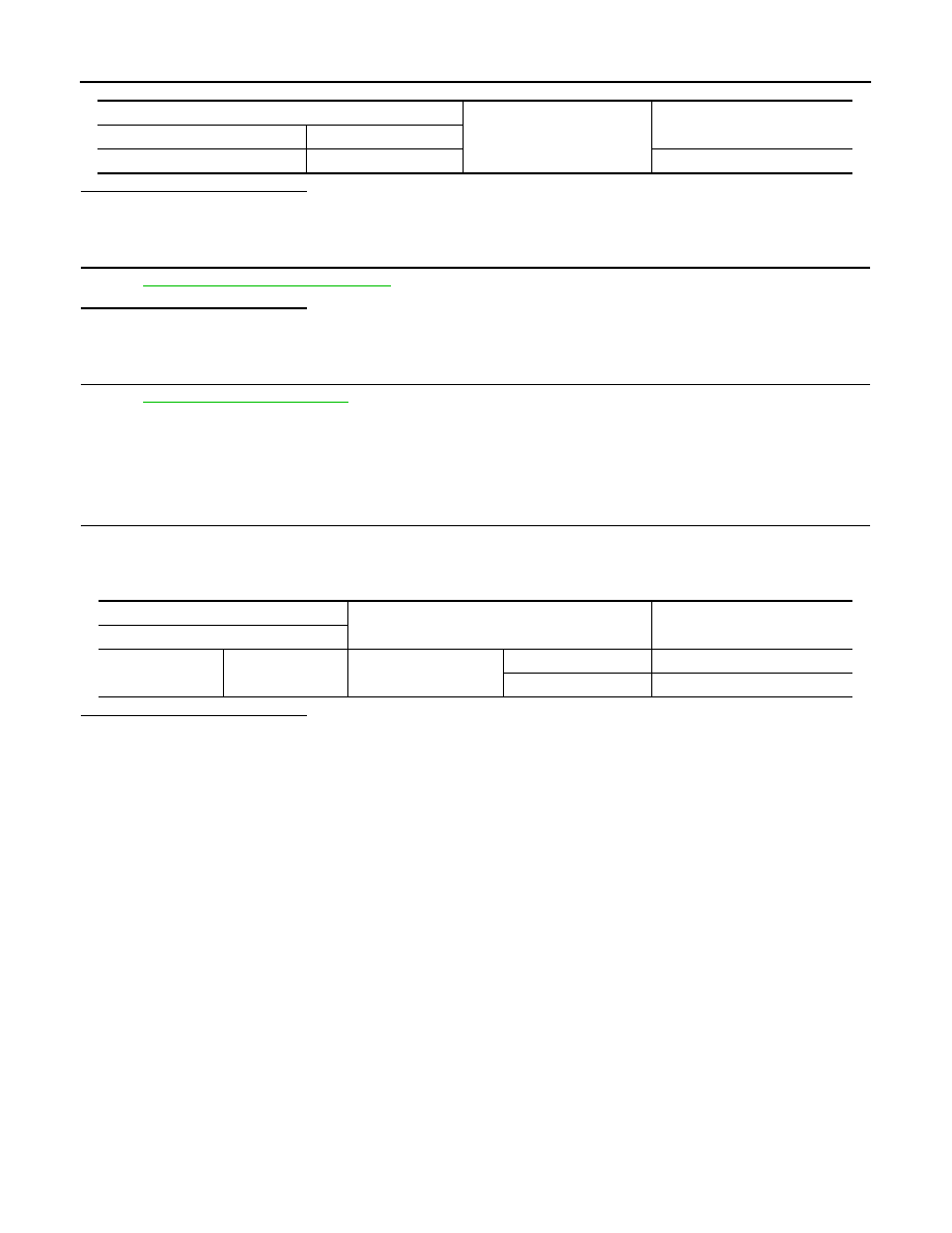
Component Inspection
INFOID:0000000009649204
1.
CHECK AUTOMATIC BACK DOOR CLOSE SWITCH
1.
Turn ignition switch OFF.
2.
Disconnect automatic back door close switch connector.
3.
Check continuity between automatic back door close switch terminals.
Is the inspection result normal?
YES
>> INSPECTION END
NO
>> Replace automatic back door close switch.
Automatic back door close switch
Ground
Continuity
Connector
Terminal
D169
2
Existed
Automatic back door close switch
Condition
Continuity
Terminal
1
2
Automatic back door
close switch
Pressed
Existed
Released
Not existed