Nissan Quest E52. Manual - part 385
DLK-254
< DTC/CIRCUIT DIAGNOSIS >
SLIDING DOOR LOCK ACTUATOR
Is the inspection result normal?
YES
>> Replace sliding door lock assembly.
NO
>> GO TO 2.
2.
CHECK DOOR LOCK ACTUATOR CIRCUIT
1.
Disconnect BCM, all door lock actuators connector.
2.
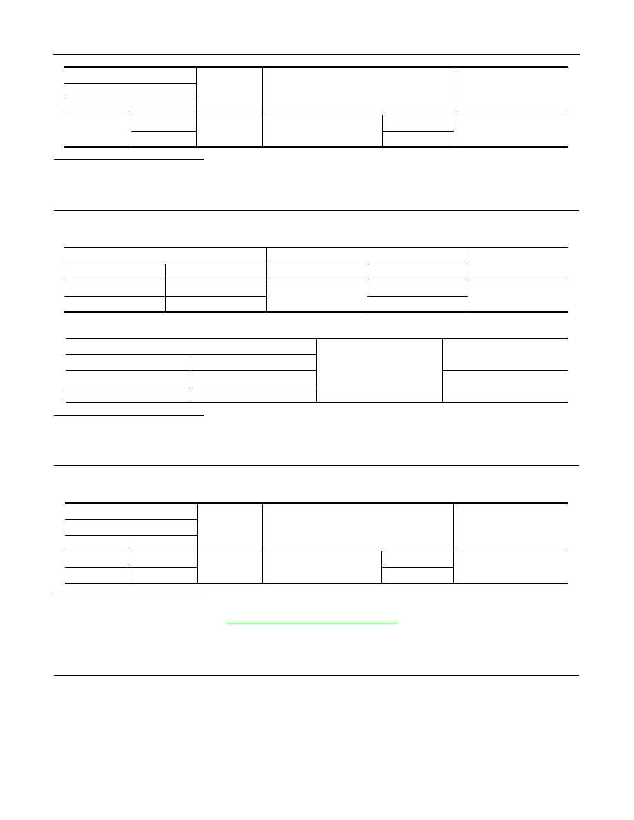
Check continuity between BCM harness connector and sliding door lock assembly RH harness connector.
3.
Check continuity between BCM harness connector and ground.
Is the inspection result normal?
YES
>> GO TO 3.
NO
>> Repair or replace harness.
3.
CHECK BCM OUTPUT SIGNAL
1.
Connect BCM connector.
2.
Check voltage between BCM harness connector and ground.
Is the inspection result normal?
YES
>> Check for internal short of door lock actuator.
NO
>> Replace BCM. Refer to
BCS-98, "Removal and Installation"
WITH AUTOMATIC SLIDING DOOR : Component Inspection
INFOID:0000000009649162
1.
CHECK SELECTIVE UNLOCK RELAY
1.
Turn ignition switch OFF.
2.
Remove selective unlock relay.
(+)
(–)
Condition
Voltage
Sliding door lock assembly RH
Connector
Terminal
D105
1
Ground
Door lock and unlock switch
Lock
9 - 16 V
2
Unlock
BCM
Sliding door lock assembly RH
Continuity
Connector
Terminal
Connector
Terminal
M123
65
D105
1
Existed
M122
55
2
BCM
Ground
Continuity
Connector
Terminal
M123
65
Not existed
M122
55
(+)
(–)
Condition
Voltage
BCM
Connector
Terminal
M123
65
Ground
Door lock and unlock switch
Lock
9 - 16 V
M122
55
Unlock