Nissan Quest E52. Manual - part 382


  Index      Nissan     Nissan Quest E52 (2011-2014 year) - Service and Repair Manual


Search            


Content   ..  380  381  382  383   ..


Nissan Quest E52. Manual - part 382


DLK-242

< DTC/CIRCUIT DIAGNOSIS >

DOOR SWITCH

3.

Check continuity between door switch harness connector and ground.

Is the inspection result normal?

YES

>> Replace BCM. Refer to 

BCS-98, "Removal and Installation"

.

NO

>> Repair or replace harness.

3.

CHECK DOOR SWITCH 

Refer to 

DLK-242, "Component Inspection"

.

Is the inspection result normal?

YES

>> GO TO 4.

NO

>> Replace malfunctioning door switch.

4.

CHECK INTERMITTENT INCIDENT

Refer to 

GI-42, "Intermittent Incident"

.

>> INSPECTION END 

Component Inspection

INFOID:0000000009649147

1.

CHECK DOOR SWITCH

1.

Turn ignition switch OFF.

2.

Disconnect malfunctioning door switch connector.

3.

Check continuity between door switch terminals.

Is the inspection result normal?

YES

>> INSPECTION END

NO

>> Replace malfunction door switch.
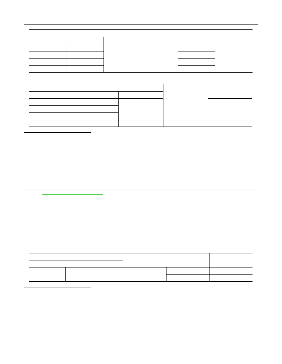
Door switch

BCM

Continuity 

Connector

Terminal

Connector

Terminal

Driver side

B35

3

M122

47

Existed

Passenger side

B235

45

Sliding LH

B71

48

Sliding RH

B221

46

Door switch

Ground

Continuity 

Connector

Terminal

Driver side

B35

3

Not existed

Passenger side

B235

Sliding LH

B71

Sliding RH

B221

Door switch

Condition

Continuity

Terminal

3

Ground part of door switch

Door switch

Pressed

Existed

Released

Not existed

BACK DOOR SWITCH

DLK-243

< DTC/CIRCUIT DIAGNOSIS >

C

D

E

F

G

H

I

J

L

M

A

B

DLK

N

O

P

BACK DOOR SWITCH

Component Function Check

INFOID:0000000009649148

1.

CHECK FUNCTION

1.

Select “DOOR LOCK” of “BCM” using CONSULT.

2.

Select “DOOR SW-BK” in “DATA MONITOR” mode.

3.

Check that the function operates normally according to the following conditions.

Is the inspection result normal?

YES

>> Back door switch is OK.

NO

>> Refer to 

DLK-243, "Diagnosis Procedure"

.

Diagnosis Procedure

INFOID:0000000009649149

1.

CHECK BACK DOOR SWITCH INPUT SIGNAL

1.

Turn ignition switch OFF.

2.

Disconnect back door lock assembly connector.

3.

Check signal between back door lock assembly harness connector and ground using oscilloscope.

Is the inspection result normal?

YES

>> GO TO 3.

NO

>> GO TO 2.

2.

CHECK BACK DOOR SWITCH CIRCUIT 

1.

Disconnect BCM connector.

2.

Check continuity between back door lock assembly harness connector and BCM harness connector.

3.

Check continuity between back door lock assembly harness connector and ground.

Is the inspection result normal?

YES

>> Replace BCM. Refer to 

BCS-98, "Removal and Installation"

.

NO

>> Repair or replace harness.

Monitor item

Condition

Status

DOOR SW-BK

Back door

Open

On

Closed

Off

(+)

(–)

Signal

(Reference value)

Back door lock assembly

Connector

Terminal

D190

7

Ground

9.0 - 10.0 V

JPMIA0593GB

Back door lock assembly

BCM

Continuity 

Connector

Terminal

Connector

Terminal

D190

7

M122

43

Existed

Back door lock assembly

Ground

Continuity 

Connector

Terminal

D190

7

Not existed

DLK-244

< DTC/CIRCUIT DIAGNOSIS >

BACK DOOR SWITCH

3.

CHECK BACK DOOR SWITCH GROUND CIRCUIT

Check continuity between back door lock assembly harness connector and ground.

Is the inspection result normal?

YES

>> GO TO 4.

NO

>> Repair or replace harness.

4.

CHECK BACK DOOR SWITCH 

Refer to 

DLK-244, "Component Inspection"

.

Is the inspection result normal?

YES

>> GO TO 5.

NO

>> Replace back door lock assembly.

5.

CHECK INTERMITTENT INCIDENT

Refer to 

GI-42, "Intermittent Incident"

.

>> INSPECTION END 

Component Inspection

INFOID:0000000009649150

1.

CHECK BACK DOOR SWITCH

1.

Turn ignition switch OFF.

2.

Disconnect back door lock assembly connector.

3.

Check continuity between back door lock assembly terminals.

Is the inspection result normal?

YES

>> INSPECTION END

NO

>> Replace back door lock assembly.

Back door lock assembly

Ground

Continuity 

Connector

Terminal

D190

8

Existed

Back door lock assembly

Condition

Continuity

Terminal

7

8

Back door lock 

Lock

Existed

Unlock

Not existed

DOOR LOCK AND UNLOCK SWITCH

DLK-245

< DTC/CIRCUIT DIAGNOSIS >

C

D

E

F

G

H

I

J

L

M

A

B

DLK

N

O

P

DOOR LOCK AND UNLOCK SWITCH

WITH AUTOMATIC SLIDING DOOR

WITH AUTOMATIC SLIDING DOOR : Component Function Check

INFOID:0000000009649151

1.

CHECK FUNCTION

1.

Select “DOOR LOCK” of “BCM” using CONSULT.

2.

Select “CDL LOCK SW”, “CDL UNLOCK SW” in “DATA MONITOR” mode.

3.

Check that the function operates normally according to the following conditions.

Is the inspection result normal?

YES

>> Door lock and unlock switch is OK.

NO

>> Refer to 

DLK-245, "WITH AUTOMATIC SLIDING DOOR : Diagnosis Procedure"

.

WITH AUTOMATIC SLIDING DOOR : Diagnosis Procedure

INFOID:0000000009649152

1.

CHECK POWER WINDOW OPERATION

1.

Turn ignition switch ON.

2.

Check power window operation.

Does power window operate?

YES

>> Replace the malfunctioning power window switch.

NO

>> Refer to 

PWC-52, "POWER WINDOW MAIN SWITCH : Diagnosis Procedure"

 (power window

main switch), 

PWC-53, "FRONT POWER WINDOW SWITCH (PASSENGER SIDE) : Diagnosis

Procedure"

 [front power window switch (passenger side)].

WITHOUT AUTOMATIC SLIDING DOOR

WITHOUT AUTOMATIC SLIDING DOOR : Component Function Check

INFOID:0000000009649153

1.

CHECK FUNCTION

1.

Select “DOOR LOCK” of “BCM” using CONSULT.

2.

Select “CDL LOCK SW”, “CDL UNLOCK SW” in “DATA MONITOR” mode.

3.

Check that the function operates normally according to the following conditions.

Is the inspection result normal?

YES

>> Door lock and unlock switch is OK.

NO

>> Refer to 

DLK-245, "WITHOUT AUTOMATIC SLIDING DOOR : Diagnosis Procedure"

.

WITHOUT AUTOMATIC SLIDING DOOR : Diagnosis Procedure

INFOID:0000000009649154

POWER WINDOW MAIN SWITCH

1.

CHECK DOOR LOCK AND UNLOCK SWITCH INPUT SIGNAL

1.

Turn ignition switch OFF.

Monitor item

Condition

Status

CDL LOCK SW 

Door lock and unlock switch

Lock

ON

Unlock

OFF

CDL UNLOCK SW 

Lock

OFF

Unlock

ON

Monitor item

Condition

Status

CDL LOCK SW 

Door lock and unlock switch

Lock

ON

Unlock

OFF

CDL UNLOCK SW 

Lock

OFF

Unlock

ON


Content   ..  380  381  382  383   ..