Nissan Quest E52. Manual - part 289
CO-26
< REMOVAL AND INSTALLATION >
WATER OUTLET AND WATER PIPING
WATER OUTLET AND WATER PIPING
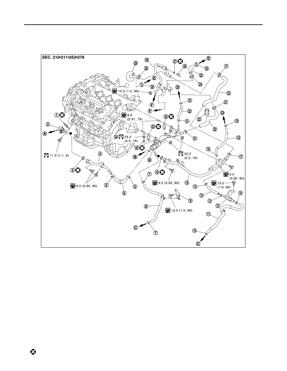
Exploded View
INFOID:0000000009650557
1.
Gasket
2.
Water connector
3.
O-ring
4.
Water bypass pipe
5.
Clamp
6.
Water hose
7.
Clamp
8.
Water hose
9.
Bracket
10. Clamp
11.
Water hose
12.
Heater thermostat
13. Clamp
14.
Water hose
15.
Heater pipe
16. O-ring
17.
Clamp
18.
Water hose
19. Clamp
20.
Heater hose
21.
Clamp
22. Clip
23.
Heater hose
24.
Clamp
25. Heater hose
26.
Air bleeder plug
27.
O-ring
28. Heater pipe
29.
Heater hose
30.
Clamp
31. Clamp
32.
Water hose
33.
Gasket
34. Engine coolant temperature sensor
35.
Gasket
36.
Water outlet
37. Bracket
A.
To oil cooler
B.
To radiator
C.
To CVT fluid warmer
D.
To electric throttle control actuator
E.
To heater core
F.
To rear heater
: Always replace after every disassembly.
JPBIA4661GB