Nissan Quest E52. Manual - part 224


  Index      Nissan     Nissan Quest E52 (2011-2014 year) - Service and Repair Manual


Search            


Content   ..  222  223  224  225   ..


Nissan Quest E52. Manual - part 224


BR-40

< REMOVAL AND INSTALLATION >

FRONT DISC BRAKE

7.

Perform inspection after installation. Refer to 

BR-42, "BRAKE CALIPER ASSEMBLY : Inspection"

.

BRAKE CALIPER ASSEMBLY : Disassembly and Assembly

INFOID:0000000009651839

DISASSEMBLY

CAUTION:

Never drop the parts.
NOTE:
Never remove the torque member, brake pad, pad return spring and pad retainers when disassembling and
assembling the cylinder body.

1.

Remove the sliding pin bolt, and remove the cylinder body from the torque member. Refer to 

BR-35,

"BRAKE PAD : Removal and Installation"

.

CAUTION:

Fix the brake pad at suitable tape so that the brake pad will not drop.

2.

Remove sliding pin boots from torque member.
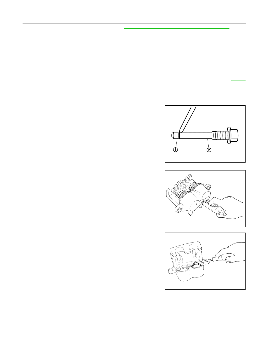
3.

Remove bushing (1) from sliding pin bolt (2).

4.

Place a wooden block as shown in the figure, and blow air from
union bolt mounting hole to remove pistons and piston boots.

CAUTION:

Never get fingers caught in the pistons.

5.

Remove piston seal from cylinder body using seal pick tool.

CAUTION:

Be careful not to damage a cylinder inner wall.

6.

Remove bleeder valve and cap.

7.

Perform inspection after disassembly. Refer to 

BR-42, "BRAKE

CALIPER ASSEMBLY : Inspection"

.

ASSEMBLY

CAUTION:

Never drop the parts.

1.

Install bleeder valve and cap.

JSFIA0496ZZ

BRB0032D

SFIA0141E

FRONT DISC BRAKE

BR-41

< REMOVAL AND INSTALLATION >

C

D

E

G

H

I

J

K

L

M

A

B

BR

N

O

P

2.

Apply rubber grease to piston seals (1), and install them to cylin-
der body.

CAUTION:

Never reuse piston seals.

3.

Apply rubber grease to piston boots (1). Cover the piston (2) end
with piston boot, and then install cylinder side lip on piston boot
securely into a groove on cylinder body.

CAUTION:

Never reuse piston boots.

4.

Apply new brake fluid to pistons (1). Push piston into cylinder
body by hand and push piston boot (2) piston-side lip into the
piston groove.

CAUTION:

Press the pistons evenly and vary the pressing point to pre-
vent cylinder inner wall from being rubbed.

5.

Apply rubber grease to mating faces (A) between sliding pin bolt
(1) and bushing (2), and install bushing to sliding pin bolt.

JPFIA0032ZZ

JPFIA0033ZZ

JPFIA0034ZZ

JSFIA0497ZZ

BR-42

< REMOVAL AND INSTALLATION >

FRONT DISC BRAKE

6.

Apply rubber grease to mating faces (A) between sliding pin bolt
(1) and sliding pin boot (2), and install sliding pin boot to torque
member.

7.

Install the cylinder body to torque member, and tighten sliding
pin bolts to the specified torque.

BRAKE CALIPER ASSEMBLY : Inspection

INFOID:0000000009651840

INSPECTION AFTER DISASSEMBLY

Check the following items and replace if necessary.

Cylinder Body

Check the inner wall of the cylinder for rust, wear, cracks or damage.

CAUTION:

Always clean with new brake fluid. Never clean with mineral oil such as gasoline and light oil.

Torque Member

Check the torque member for rust, wear, cracks or damage.

Pistons

Check the surface of the piston for rust, wear, cracks or damage.

CAUTION:

A piston sliding surface is plated. Never polish with sandpaper.

Sliding Pin Bolt, Sliding Pin Boot and Bushing

Check the sliding pin bolts, sliding boots and bushing for rust, wear, cracks or damage.

INSPECTION AFTER INSTALLATION

• Check a drag of front disc brake. If any drag is found, follow the procedure described below.
1.

Remove brake pads. Refer to 

BR-35, "BRAKE PAD : Removal and Installation"

.

2.

Press the pistons. Refer to 

BR-35, "BRAKE PAD : Removal and Installation"

.

3.

Install brake pads. Refer to 

BR-35, "BRAKE PAD : Removal and Installation"

.

4.

Securely depress the brake pedal several times.

5.

Check a drag of front disc brake again. If any drag is found, disassemble the cylinder body and replace if
necessary. Refer to 

BR-40, "BRAKE CALIPER ASSEMBLY : Disassembly and Assembly"

.

• Burnish contact surface between disc rotor and brake pads after refinishing or replacing disc rotor or brake

pad, or if a soft pedal occurs at very low mileage. Refer to 

BR-14, "DISC ROTOR : Inspection and Adjust-

ment"

.

JSFIA0498ZZ

REAR DISC BRAKE

BR-43

< REMOVAL AND INSTALLATION >

C

D

E

G

H

I

J

K

L

M

A

B

BR

N

O

P

REAR DISC BRAKE

BRAKE PAD

BRAKE PAD : Exploded View

INFOID:0000000009651841

Molykote is a registered trademark of Dow Corning Corporation.

BRAKE PAD : Removal and Installation

INFOID:0000000009651842

REMOVAL

WARNING:

Since dust covering the rear brake has an affect on human body, the dust must be removed with a
dust collector. Never splatter the dust with an air blow gun.

CAUTION:

• Never depress the brake pedal while removing the brake pads because the piston may pop out.
• If the brake fluid or grease adheres to the disc rotor or the cylinder body, quickly wipe it off.

1.

Remove tires with power tool.

2.

Remove sliding pin bolt (upper side).

1.

Sliding pin bolt

2.

Cylinder body

3.

Inner shim cover

4.

Inner shim

5.

Inner pad (with pad wear sensor)

6.

Pad retainer

7.

Torque member

8.

Outer pad

9.

Outer shim

10.

Outer shim cover

1 Apply rubber grease.

2: Apply MOLYKOTE

®

 AS880N or silicone-based grease.

3: Apply MOLYKOTE

®

 7439 or equivalent.

: N·m (kg-m, ft-lb)

JSFIA0586GB

JSFIA0587ZZ


Content   ..  222  223  224  225   ..