Nissan Quest E52. Manual - part 162


  Index      Nissan     Nissan Quest E52 (2011-2014 year) - Service and Repair Manual


Search            


Content   ..  160  161  162  163   ..


Nissan Quest E52. Manual - part 162


AV

INSPECTION AND ADJUSTMENT

AV-527

< BASIC INSPECTION >

[BOSE AUDIO WITH NAVIGATION]

C

D

E

F

G

H

I

J

K

L

M

B

A

O

P

NOTE:
AVM: Around view monitor

CONFIGURATION (AROUND VIEW MONITOR CONTROL UNIT)

CONFIGURATION (AROUND VIEW MONITOR CONTROL UNIT) : Work Procedure

INFOID:0000000009942945

1.

SAVING VEHICLE SPECIFICATION

CONSULT Configuration

Perform “Before Replace ECU”, and save the current vehicle specification in CONSULT.
Is the vehicle specification saved normally?

YES

>> GO TO 2.

NO

>> GO TO 4.

2.

REPLACE AROUND VIEW MONITOR CONTROL UNIT

Replace around view monitor control unit. Refer to 

AV-631, "Removal and Installation"

.

>> GO TO 3.

3.

WRITING VEHICLE SPECIFICATION

CONSULT Configuration

Select “Configuration” or “After Replace ECU”, and write the vehicle specification saved in CONSULT to
around view monitor control unit.

>> GO TO 6.

4.

REPLACE AROUND VIEW MONITOR CONTROL UNIT

Replace around view monitor control unit. Refer to 

AV-631, "Removal and Installation"

.

>> GO TO 5.

5.

WRITE VEHICLE SPECIFICATION

CONSULT Configuration

Select “Manual Configuration”, and write the vehicle specification to around view monitor control unit.
NOTE:
Around view monitor control unit does not have any setting items. Selection of items on “Manual Configura-
tion” screen is not required.

>> GO TO 6.

6.

PERFORM SELF-DIAGNOSIS

CONSULT Self Diagnostic Result

Perform self-diagnosis of CONSULT, and check whether or not DTC U1305 is detected.

Is DTC U1305 detected?
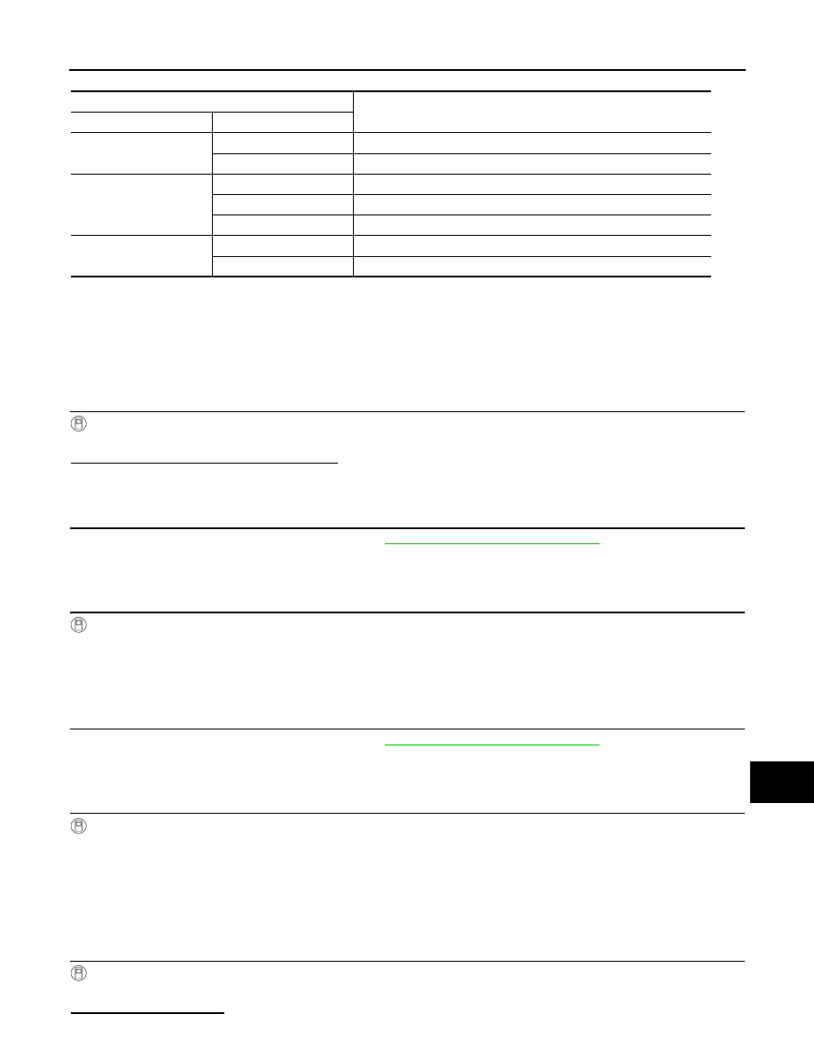
MANUAL SETTING ITEM

Detail

Items

Setting value

STEERING

LHD

LHD models 

RHD

RHD models

CAMERA SYSTEM

NONE/AVM

Without camera system or with around view monitor system

REAR CAMERA

With rear view monitor system

REAR+SIDE

With rear view monitor system and front-side view monitor function

SOUND SYSTEM

BASE

Without BOSE system

BOSE

With BOSE system

AV-528

< BASIC INSPECTION >

[BOSE AUDIO WITH NAVIGATION]

INSPECTION AND ADJUSTMENT

>> GO TO 5.
>> GO TO 7.

7.

OPERATION CHECK

Check that the operation of the around view monitor control unit and camera images (fixed guide lines and
predictive course lines) are normal.

>> WORK END

PREDICTIVE COURSE LINE CENTER POSITION ADJUSTMENT

PREDICTIVE COURSE LINE CENTER POSITION ADJUSTMENT : Description

INFOID:0000000009942946

Adjust the center position of the predictive course line of the rear view monitor if it is shifted.

PREDICTIVE COURSE LINE CENTER POSITION ADJUSTMENT : Work Procedure

INFOID:0000000009942947

1.

DRIVING

Drive the vehicle straight ahead 100 m (328.1 ft) or more at a speed of 30 km/h (18.6 MPH) or more.

>> END

CALIBRATING CAMERA IMAGE (AROUND VIEW MONITOR)

CALIBRATING CAMERA IMAGE (AROUND VIEW MONITOR) : Description

INFOID:0000000009942948

• Calibration must be performed after removing/replacing the cameras, removing parts (e.g. front grille, door

mirror, and others) mounted on the cameras, or replacing the Around view monitor control unit.

• The use of CONSULT is required to perform calibration or writing of calibration results to the Around view

monitor control unit.

• Align the white lines on the road near the vehicle at the boundary of each camera image by this camera cal-

ibration. The white lines far from the vehicle may not be aligned at the boundary of each camera image. The
farther the line, the greater the difference is. 

CALIBRATING CAMERA IMAGE (AROUND VIEW MONITOR) : Work Procedure

INFOID:0000000009942949

CALIBRATION FLOWCHART

AV

INSPECTION AND ADJUSTMENT

AV-529

< BASIC INSPECTION >

[BOSE AUDIO WITH NAVIGATION]

C

D

E

F

G

H

I

J

K

L

M

B

A

O

P

Following the flowchart shown in the figure, perform the calibration. 

NOTE:
View in the incomplete calibration state is indicated by “

” on the

around view monitor.

CALIBRATION PROCEDURE

1.

AROUND VIEW MONITOR SCREEN CONFIRMATION

Check that there is no indication of “Incomplete calibration”.

Is the “Incomplete calibration” display visible?

YES

>> GO TO 2.

NO

>> GO TO 4.

2.

CHECK THAT AROUND VIEW MONITOR CONTROL UNIT IS REPLACED

Check that the around view monitor control unit is replaced.

Is the around view monitor control unit replaced?

YES

>> GO TO 3.

NO

>> GO TO 5.

JSNIA4210GB

JSNIA4606ZZ

JSNIA4606ZZ

AV-530

< BASIC INSPECTION >

[BOSE AUDIO WITH NAVIGATION]

INSPECTION AND ADJUSTMENT

3.

CANCEL THE INDICATION OF INCOMPLETE CALIBRATION (PERFORM THIS ONLY AFTER REPLAC-

ING AROUND VIEW MONITOR CONTROL UNIT.)

CONSULT work support

1.

On the CONSULT screen, touch “CALIBRATING CAMERA IMAGE (FRONT CAMERA)”, “CALIBRATING
CAMERA IMAGE (PASS-SIDE CAMERA)”, “CALIBRATING CAMERA IMAGE (DR-SIDE CAMERA)”, or
“CALIBRATING CAMERA IMAGE (REAR CAMERA)” to accept the selection.
NOTE:
To cancel the indication of Incomplete calibration, select items based on the target camera. 

2.

On the adjustment screen of each camera, touch “APPLY” but-
ton. After this, touch “OK” button.

CAUTION:

• Never perform operations other than those mentioned

above.

• Never perform “Initialize Camera Image Calibration”. 

3.

Display the around view monitor screen to check that there is no
errors, such as deviations among the camera images.

Is there a malfunction?

YES

>> Calibration end

NO

>> GO TO 1.

4.

PERFORM SIMPLIFIED CONFIRMATION/ADJUSTMENT BY “FINE TUNING OF BIRDS-EYE VIEW”

1.

Put target line 1 on the ground beside each axle using packing tape, etc. 

2.

Put target lines 2 equal to the vehicle total length + approximately 1.0 m (39.3 in) from the vehicle side
(right and left) at approximately 30 cm (11.8 in) away from the vehicle (make the line as parallel with the
vehicle as possible) 

Preparation of simplified target line

3.

CONSULT work support

Touch “FINE TUNING OF BIRDS-EYE VIEW” on the CONSULT screen.

4.

On the CONSULT screen, touch “SELECT” button to select right or left camera and perform camera cali-
bration as instructed below:

-

If the marker on the screen deviates from Target line 1, touch “AXIS X” button and “AXIS Y” button to
adjust so that the marker is placed on the Target line 1.   

-

If Target line 2 is misaligned among the cameras, adjust each camera image to bring Target line 2 into a
straight line.

CAUTION:

Never adjust the front camera and rear camera. Only adjust the right and left cameras. 

JSNIA4212ZZ

JSNIA0927ZZ

1.

Target lines 1

2.

Target lines 2

A.

Approx. 30 cm (11.8 in)

B.

Approx. 1.0 m (39.3 in)


Content   ..  160  161  162  163   ..