Nissan Quest E52. Manual - part 150


  Index      Nissan     Nissan Quest E52 (2011-2014 year) - Service and Repair Manual


Search            


Content   ..  148  149  150  151   ..


Nissan Quest E52. Manual - part 150


AV

DIAGNOSIS SYSTEM (AROUND VIEW MONITOR CONTROL UNIT)

AV-479

< SYSTEM DESCRIPTION >

[BOSE AUDIO WITH NAVIGATION]

C

D

E

F

G

H

I

J

K

L

M

B

A

O

P

Calibrating Camera Image (front camera, pass-side camera, dr-side camera, and rear camera)

Perform the calibration of camera image caused by the incorrect
mounting position of each camera, etc. Always perform calibration
after performing the following work.
• When each camera or each camera mount (e.g. front grille, door

mirror, and others) is removed

• When replacing the around view monitor control unit
Refer to 

AV-528, "CALIBRATING CAMERA IMAGE (AROUND VIEW

MONITOR) : Work Procedure"

 for the calibration procedure. 

Initialize Camera Image Calibration

The calibration can be initialized to NISSAN factory shipment condition.

Select Language of Warning Message

No need to be selected because it can change the language on setting of Navi by customer.

Predictive Course Line Display

ON/OFF setting of predictive course line can be performed.

Steering Angle Sensor Adjustment

Steering angle sensor neutral position can be adjusted and registered.

CAUTION:

For vehicles with VDC, adjust the steering angle sensor neutral position on the ABS actuator control
unit side.

Non-Viewable Area Reminder

ON/OFF setting of the non-viewable area reminder can be performed.

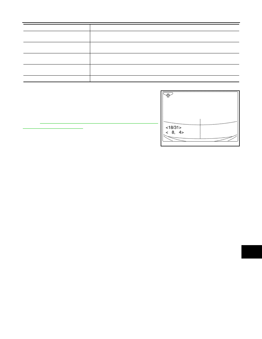
FINE TUNING OF BIRDS-EYE VIEW

The confirmation and adjustment of the difference between each camera can be per-
formed.

SELECT LANGUAGE OF WARNING 
MESSAGE

Language of warning message shown during camera image display can be selected.

PREDICTIVE COURSE LINE DIS-
PLAY 

ON/OFF setting of predictive course line can be performed.

STEERING ANGLE SENSOR AD-
JUSTMENT

Steering angle sensor neutral position can be adjusted and registered.

NON-VIEWABLE AREA REMINDER

ON/OFF setting of the non-viewable area reminder can be performed.

Work support item

Function

JSNIA4212ZZ

Adjustment range

Rotating direction

: 31 patterns (16 on the center)

Upper/lower direction

: (

22) – (+22)

Left/right direction

: (

22) – (+22)

AV-480

< ECU DIAGNOSIS INFORMATION >

[BOSE AUDIO WITH NAVIGATION]

AV CONTROL UNIT

ECU DIAGNOSIS INFORMATION

AV CONTROL UNIT

Reference Value

INFOID:0000000009652279

VALUES ON THE DIAGNOSIS TOOL

NOTE:
The following table includes information (items) inapplicable to this vehicle. For information (items) applicable
to this vehicle, refer to CONSULT display items.

CONSULT MONITOR ITEM

TERMINAL LAYOUT

Monitor Item

Condition

Value/Status

VHCL SPD SIG

Ignition switch 
ON

Vehicle speed > 0 km/h (0 MPH)

On

Vehicle speed = 0 km/h (0 MPH)

Off

PKB SIG

Ignition switch 
ON

Parking brake is applied.

On

Parking brake is released.

Off

ILLUM SIG

Ignition switch 
ON

Lighting switch is ON

On

Lighting switch is OFF

Off

IGN SIG

Ignition switch 
ON

On

Ignition switch 
ACC

Off

REV SIG

Ignition switch 
ON

Selector lever is in R position

On

Selector lever is in any position other than R

Off

SIDE VIEW SW

Ignition switch 
ON

This item is displayed, but cannot be moni-
tored.

Off

ROOM LAMP

Ignition switch 
ON

This item is displayed, but cannot be moni-
tored.

Off

JSNIA5399ZZ

AV

AV CONTROL UNIT

AV-481

< ECU DIAGNOSIS INFORMATION >

[BOSE AUDIO WITH NAVIGATION]

C

D

E

F

G

H

I

J

K

L

M

B

A

O

P

PHYSICAL VALUES

Terminal

(Wire color)

Description

Condition

Standard

Reference value

(Approx.)

+

Signal name

Input/

Output

1

(LG)

20

(B)

Amp. ON signal

Input

Ignition 

switch 

ON

9.0 – 16.0 V

12.0 V

2

(R)

3

(G)

Sound signal 
front LH

Output

Ignition 

switch 

ON

Sound output

Outputs 
waveform 
synchronized 
with sound.

4

(B)

5

(W)

Sound signal rear 
LH

Output

Ignition 

switch 

ON

Sound output

Outputs 
waveform 
synchronized 
with sound.

6

(L)

15

(GR)

Steering switch 
signal A

Input

Ignition 

switch 

ON

Keep pressing 
SOURCE switch.

0 - 5.5 V

0 V

Keep pressing MENU 
UP switch.

1.0 V

Keep pressing MENU 
DOWN switch.

2.0 V

Keep pressing 


switch.

3.0 V

Keep pressing ENTER 
switch.

4.0 V

Except for above.

5.0 V

7

(O)

20

(B)

ACC power sup-
ply

Input

Ignition 

switch 

ACC

7.0 – 16.0 V

Battery voltage

10

(GR)

Shield

11

(W)

12

(B)

Sound signal 
front RH

Output

Ignition 

switch 

ON

Sound output

Outputs 
waveform 
synchronized 
with sound.

13

(BR)

14

(Y)

Sound signal rear 
RH

Output

Ignition 

switch 

ON

Sound output

Outputs 
waveform 
synchronized 
with sound.

SKIB3609E

SKIB3609E

SKIB3609E

SKIB3609E

AV-482

< ECU DIAGNOSIS INFORMATION >

[BOSE AUDIO WITH NAVIGATION]

AV CONTROL UNIT

16

(P)

15

(GR)

Steering switch 
signal B

Input

Ignition 

switch 

ON

Keep pressing VOL 
DOWN switch.

0 – 5.5 V

0 V

Keep pressing VOL UP 
switch.

1.0 V

Keep pressing 


switch.

2.0 V

Keep pressing 


switch.

3.0 V

Except for above.

5.0 V

19

(SB)

20

(B)

Battery power 
supply

Input

Ignition 

switch 

OFF

9.0  – 16.0 V

Battery voltage

22

(G)

42

(R)

Camera power 
supply

Output

Ignition 

switch 

ON

“Camera” switch is ON 
or selector lever is in “R” 
position.

5.9  – 6.5 V

6.0 V

26

(BR)

46

(Y)

AUX image sig-
nal

Input

Ignition 

switch 

ON 

When AUX image is dis-
played on front or rear 
display unit.

Waveform ac-
cording to 
AUX image is 
input.

29

(BR)

49

(W)

Disk eject signal

Input

Ignition 

switch 

ON 

Keep pressing disk eject 
switch.

1.5 V or less

0 V

Except for above.

5.0 V or more

5.0 V

34

(W)

33

(B)

Composite im-
age signal (for 
rear display unit)

Input

Ignition 

switch 

ON 

When DVD, USB or 
AUX image is displayed 
on rear display unit.

Waveform ac-
cording to 
composite im-
age is input.

47

Shield

53

Shield

65

(W)

20

(B)

Parking brake 
signal

Input

Ignition 

switch 

ON

Parking brake is ap-
plied.

1.5 V or less

0 V

Parking brake is re-
leased.

3.5 V or more

Terminal

(Wire color)

Description

Condition

Standard

Reference value

(Approx.)

+

Signal name

Input/

Output

SKIB2251J

SKIB2251J

JSNIA1938ZZ


Content   ..  148  149  150  151   ..