Content .. 1235 1236 1237 1238 ..
Nissan Quest E52. Manual - part 1237
TM-178
< UNIT DISASSEMBLY AND ASSEMBLY >
[CVT: RE0F09B]
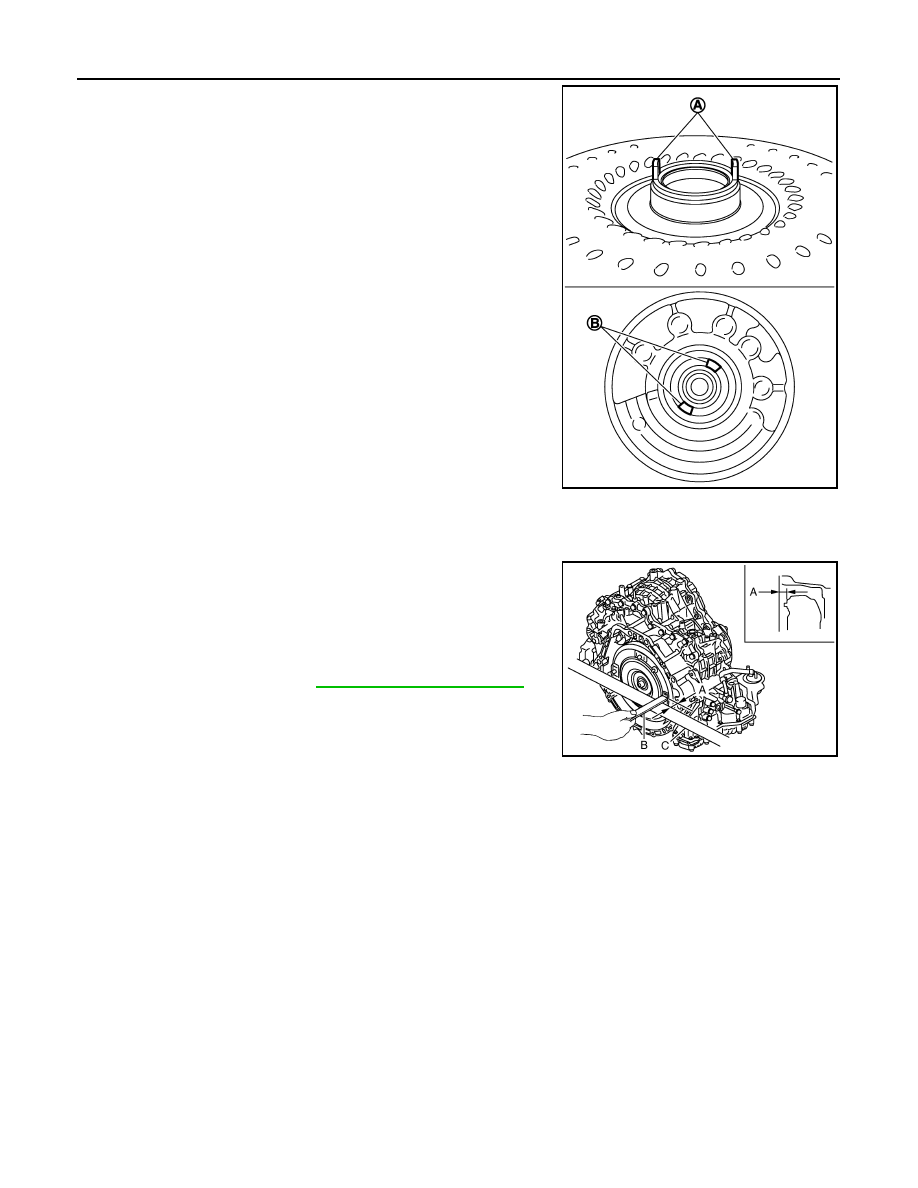
TORQUE CONVERTER
• Attach the pawl (A) of the torque converter to the inner gear hole
(B) on the oil pump side.
CAUTION:
• Rotate the torque converter for installing torque converter.
• Never damage bushing inside of torque converter sleeve
when removing torque converter.
Inspection
INFOID:0000000009650258
INSPECTION AFTER INSTALLATION
After inserting a torque converter to transaxle assembly, check
dimension (A) is within the reference value limit.
JPDIA0692ZZ
B
: Scale
C
: Straightedge
Dimension A
: Refer to
.
JPDIA0620ZZ