Content .. 1211 1212 1213 1214 ..
Nissan Quest E52. Manual - part 1213
TM-82
< DTC/CIRCUIT DIAGNOSIS >
[CVT: RE0F09B]
P0705 TRANSMISSION RANGE SWITCH A
Is the inspection result normal?
YES
>> INSPECTION END
NO
>> Replace the transaxle assembly due to malfunction in the transmission range switch. Refer to
174, "Removal and Installation"
.
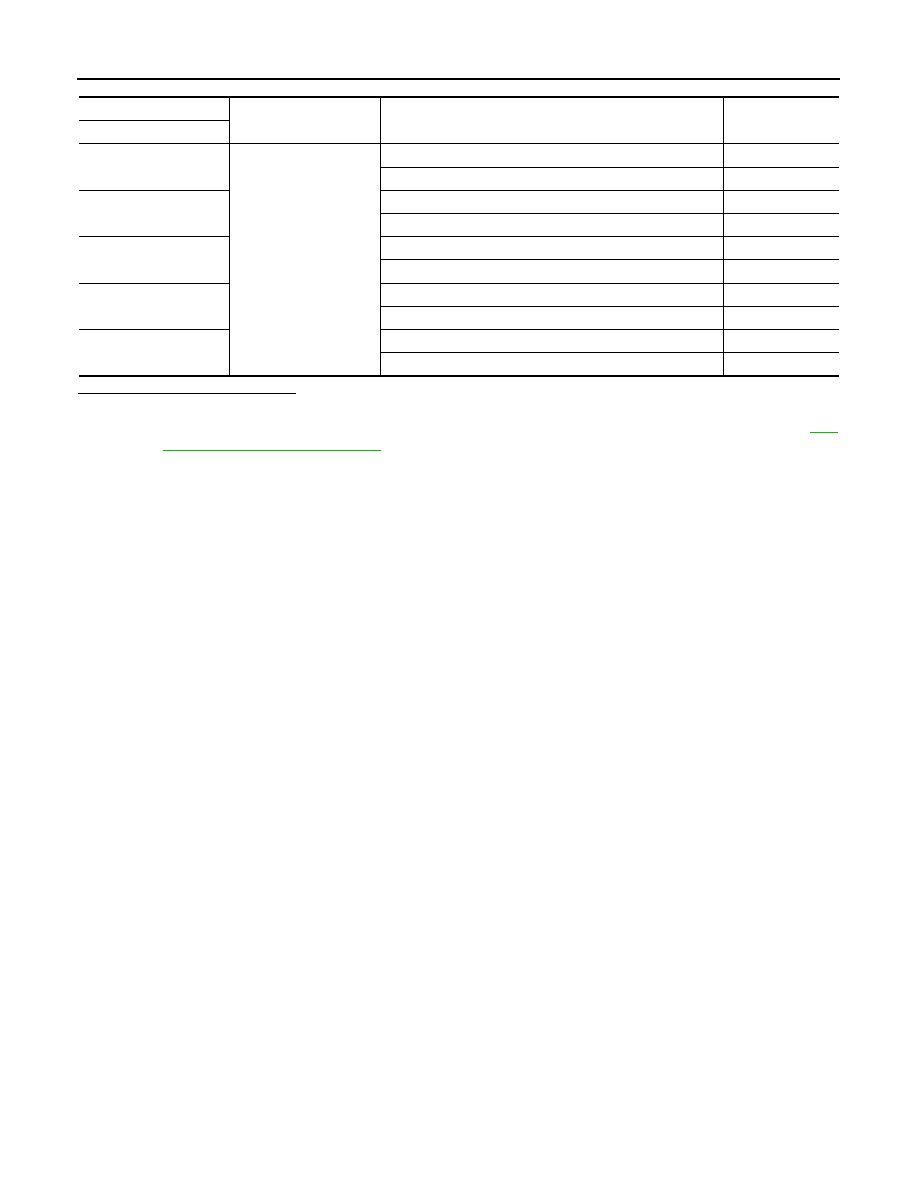
CVT unit
—
Condition
Continuity
Terminal
4
Ground
Selector lever in “N”, “D”, and “L” positions
Existed
Selector lever in other positions
Not existed
5
Selector lever in “D” and “L” positions
Existed
Selector lever in other positions
Not existed
14
Selector lever in “R” and “D” positions
Existed
Selector lever in other positions
Not existed
15
Selector lever in “D” and “L” positions
Existed
Selector lever in other positions
Not existed
18
Selector lever in “R”, “N”, and “D” positions
Existed
Selector lever in other positions
Not existed