Nissan Quest E52. Manual - part 1210


  Index      Nissan     Nissan Quest E52 (2011-2014 year) - Service and Repair Manual


Search            


Content   ..  1208  1209  1210  1211   ..


Nissan Quest E52. Manual - part 1210


TM-70

< BASIC INSPECTION >

[CVT: RE0F09B]

CVT POSITION

CVT POSITION

Inspection and Adjustment

INFOID:0000000009650120

INSPECTION

1.

Turn ignition switch ON (engine stop) when selector lever is “P” position.

2.

Check that selector lever can be shifted to other than “P” position when brake pedal is depressed. Also
check that selector lever can be shifted from “P” position only when brake pedal is depressed.

3.

Shift the selector lever and check for excessive effort, sticking, noise or rattle.

4.

Check that selector lever stops at each position with the feel of engagement when it is moved through all
the positions. Check that the actual position of selector lever matches the position shown by shift position
indicator and manual lever on the transaxle.

5.

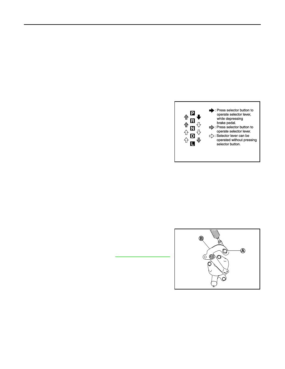
The method of operating selector lever to individual positions
correctly should be as shown.

6.

When selector button is pressed in “P”, “R”, “N”, “D” or “L” posi-
tion without applying forward/backward force to selector lever,
check button operation for sticking.

7.

Check that back-up lamps illuminate only when selector lever is
placed in the “R” position.

8.

When in “R” position, check that back-up lamps do not illuminate
even when the selector lever is in the “P” position.

CAUTION:

Check the lighting without pressing shift button.

9.

Check that back-up lamps do not illuminate when selector lever is pushed toward the “R” position when in
the “P” or “N” position.

CAUTION:

Check the lighting without pressing shift button.

10. Check that the engine can only be started with selector lever in the “P” and “N” positions.

11. Check that transaxle is locked completely in “P” position.

ADJUSTMENT

1.

Shift the selector lever to “P” position.

CAUTION:

Turn wheels more than 1/4 rotations and apply the park lock.

2.

Loosen the control cable nut (A).

3.

Place manual lever (B) to “P” position.

CAUTION:

Never apply any force to manual lever.

4.

Tighten the control cable nut. Refer to 

TM-156, "Exploded View"

.

CAUTION:

Fix manual lever when tightening.

JPDIA0343GB

JSDIA2396ZZ

U0100 LOST COMMUNICATION (ECM A)

TM-71

< DTC/CIRCUIT DIAGNOSIS >

[CVT: RE0F09B]

C

E

F

G

H

I

J

K

L

M

A

B

TM

N

O

P

DTC/CIRCUIT DIAGNOSIS

U0100 LOST COMMUNICATION (ECM A)

DTC Logic

INFOID:0000000009650121

DTC DETECTION LOGIC

DTC CONFIRMATION PROCEDURE

1.

PREPARATION BEFORE WORK

If another “DTC CONFIRMATION PROCEDURE” occurs just before, turn ignition switch OFF and wait for at
least 10 seconds, then perform the next test.

>> GO TO 2.

2.

PERFORM DTC CONFIRMATION PROCEDURE

1.

Start the engine and wait for at least 5 seconds.

2.

Check the DTC.

Is “U0100” detected?

YES

>> Go to 

TM-71, "Diagnosis Procedure"

.

NO

>> INSPECTION END

Diagnosis Procedure

INFOID:0000000009650122

For the diagnosis procedure, refer to 

LAN-17, "Trouble Diagnosis Flow Chart"

DTC

Trouble diagnosis name

DTC detection condition

Possible causes

U0100

Lost Communication With 
ECM/PCM A 

When the ignition switch is ON, TCM is un-
able to receive the CAN communications 
signal from ECM continuously for 2 sec-
onds or more.

• ECM
• Harness or connector

(CAN communication line is open or 
shorted)

TM-72

< DTC/CIRCUIT DIAGNOSIS >

[CVT: RE0F09B]

U1000 CAN COMM CIRCUIT

U1000 CAN COMM CIRCUIT

Description

INFOID:0000000009650123

CAN (Controller Area Network) is a serial communication line for real time application. It is an on-vehicle mul-
tiplex communication line with high data communication speed and excellent malfunction detection ability.
Many electronic control units are equipped onto a vehicle, and each control unit shares information and links
with other control units during operation (not independent). In CAN communication, control units are con-
nected with 2 communication lines (CAN-H and CAN-L) allowing a high rate of information transmission with
less wiring. Each control unit transmits/receives data but selectively reads required data only.

DTC Logic

INFOID:0000000009650124

DTC DETECTION LOGIC

DTC CONFIRMATION PROCEDURE

1.

PRECONDITIONING

If “DTC CONFIRMATION PROCEDURE” has been previously conducted, always turn ignition switch OFF and
wait at least 10 seconds before conducting the next test.

>> GO TO 2.

2.

CHECK DTC DETECTION

With CONSULT

1.

Turn ignition switch ON.

2.

Start engine and wait at least 5 seconds.

3.

Check DTC.

Is “U1000” detected?

YES

>> Go to 

TM-72, "Diagnosis Procedure"

.

NO

>> INSPECTION END

Diagnosis Procedure

INFOID:0000000009650125

Go to 

LAN-17, "Trouble Diagnosis Flow Chart"

.

DTC

Trouble diagnosis name

DTC detected condition

Possible cause

U1000

CAN Communication Line

When TCM is not transmitting or receiving 
CAN communication signal for 2 seconds or 
more.

Harness or connectors
(CAN communication line is open or short-
ed.)

U1010 CONTROL UNIT (CAN)

TM-73

< DTC/CIRCUIT DIAGNOSIS >

[CVT: RE0F09B]

C

E

F

G

H

I

J

K

L

M

A

B

TM

N

O

P

U1010 CONTROL UNIT (CAN)

DTC Logic

INFOID:0000000009650126

DTC DETECTION LOGIC

DTC CONFIRMATION PROCEDURE

1.

PRECONDITIONING

If “DTC CONFIRMATION PROCEDURE” has been previously conducted, always turn ignition switch OFF and
wait at least 10 seconds before conducting the next test.

>> GO TO 2.

2.

CHECK DTC DETECTION

With CONSULT

1.

Start the engine.

2.

Maintain the idling conditions for 6 seconds or more.

3.

Check DTC.

Is “U1010” detected?

YES

>> Go to 

TM-73, "Diagnosis Procedure"

.

NO

>> INSPECTION END

Diagnosis Procedure

INFOID:0000000009650127

1.

CHECK INTERMITTENT INCIDENT

Refer to 

GI-42, "Intermittent Incident"

.

Is the inspection result normal?

YES

>> Replace the TCM. Refer to 

TM-158, "Removal and Installation"

.

NO

>> Repair or replace damaged parts.

DTC

Trouble diagnosis name

DTC detected condition

Possible cause

U1010

TCM Communication Malfunction

When detecting error during the initial diag-
nosis of CAN controller to TCM

TCM


Content   ..  1208  1209  1210  1211   ..