Content .. 1190 1191 1192 1193 ..
Nissan Quest E52. Manual - part 1192
STR-18
< REMOVAL AND INSTALLATION >
STARTER MOTOR
Type: M000TA0073
NOTE:
Apply high-temperature grease to lubricate the bearing, gears and frictional surface when assembling the
starter.
Removal and Installation
INFOID:0000000009650611
REMOVAL
1.
Remove battery. Refer to
PG-105, "Removal and Installation"
.
2.
Remove air duct (inlet) and air cleaner assembly. Refer to
EM-26, "Removal and Installation"
.
3.
Disconnect TCM harness connector (1) and ECM harness con-
nectors (2).
JPBIA1777GB
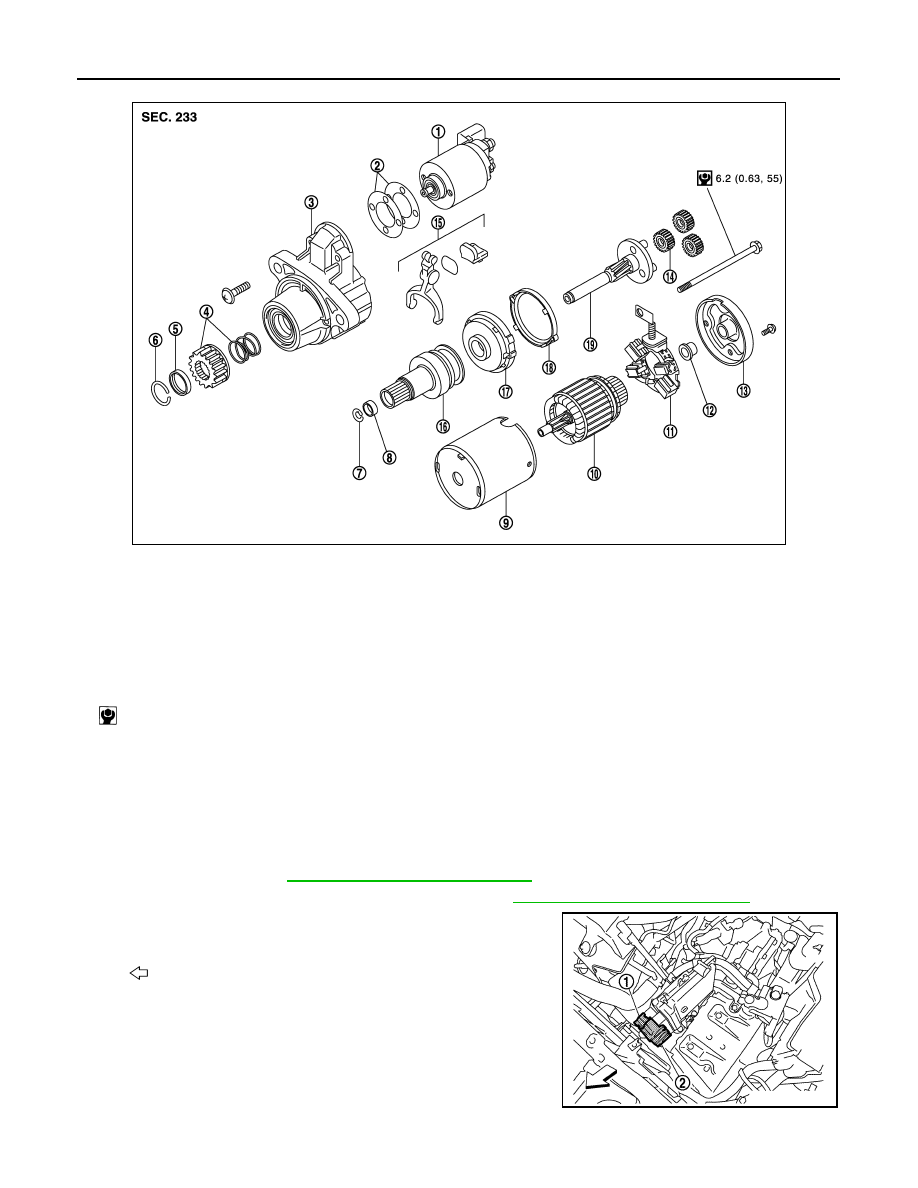
1.
Magnetic switch assembly
2.
Dust cover kit
3.
Gear case assembly
4.
Pinion assembly
5.
Stopper
6.
Ring
7.
Ring
8.
Stopper
9.
Yoke assembly
10. Armature assembly
11.
Brush holder assembly
12. Metal
13. Rear cover
14. Gear assembly
15. Shift lever set
16. Clutch gear assembly
17. Center bracket
18. Packing
19. Gear shaft
: N·m (kg-m, in-lb)
: Vehicle front
JMBIA3032ZZ