Nissan Quest E52. Manual - part 1174


  Index      Nissan     Nissan Quest E52 (2011-2014 year) - Service and Repair Manual


Search            


Content   ..  1172  1173  1174  1175   ..


Nissan Quest E52. Manual - part 1174


ST-22

< REMOVAL AND INSTALLATION >

STEERING GEAR AND LINKAGE

Removal and Installation

INFOID:0000000009648915

REMOVAL

1.

Set the vehicle to the straight-ahead position.

2.

Remove tires with power tool. Refer to 

WT-46, "Exploded View"

.

3.

Remove engine under cover. Refer to 

EXT-28, "Exploded View"

.

4.

Remove exhaust front tube. Refer to 

EX-6, "Removal and Installation"

.

5.

Remove heat insulator from front suspension member.

6.

Remove cotter pin, and then loosen the nut.
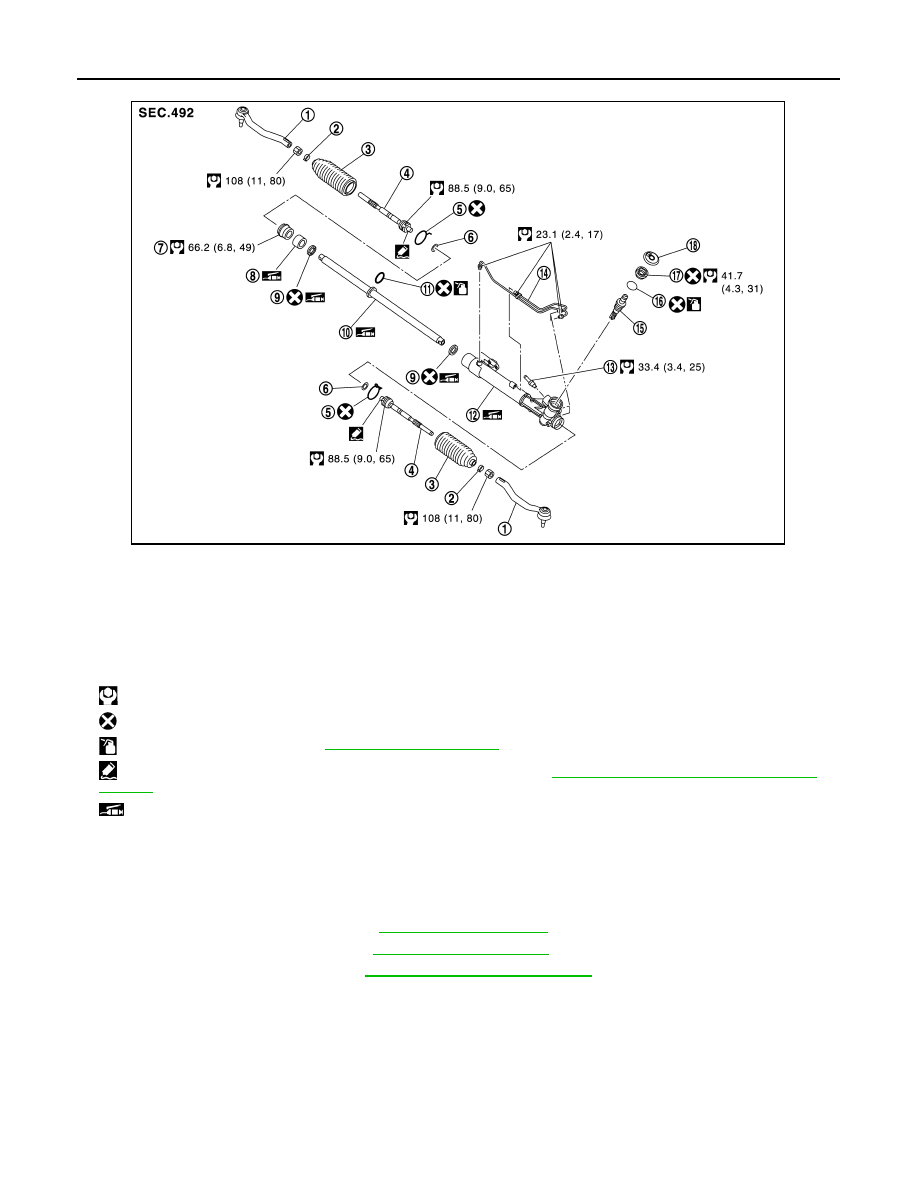
1.

Outer socket

2.

Boot clamp 

3.

Boot 

4.

Inner socket

5.

Boot clamp (stainless wire)

6.

Spacer

7.

End cover assembly

8.

Rack spacer

9.

Rack oil seal

10. Rack assembly

11.

O-ring

12. Gear housing assembly

13. Low pressure piping

14. Cylinder tubes

15. Gear-sub assembly

16. O-ring

17. Rear cover

18. Rear cover cap

: N·m (kg-m, ft-lb)

: Always replace after every disassembly.

: Apply power steering fluid. Refer to 

MA-10, "Fluids and Lubricants"

.

: Apply Genuine High Strength Thread Locking Sealant or equivalent. Refer to 

GI-22, "Recommended Chemical Products and 

Sealants"

.

: Apply multi-purpose grease.

JSGIA0936GB

STEERING GEAR AND LINKAGE

ST-23

< REMOVAL AND INSTALLATION >

C

D

E

F

H

I

J

K

L

M

A

B

ST

N

O

P

7.

Remove steering outer socket from steering knuckle so as not to
damage ball joint boot using a ball joint remover (A) (commercial
service tool).

CAUTION:

Temporarily tighten the nut to prevent damage to threads
and to prevent the ball joint remover from suddenly coming
off.

8.

Remove high pressure piping and return hose of hydraulic pip-
ing, and then drain power steering fluid.

9.

Remove intermediate shaft mounting bolt (steering gear side),
and separate intermediate shaft from steering gear assembly.

CAUTION:

• Place a matching mark on both intermediate shaft and steering gear assembly before removing

intermediate shaft.

• When removing intermediate shaft, never insert a tool, such as a screwdriver, into the yoke

groove to pull out the intermediate shaft. In case of the violation of the above, replace intermedi-
ate shaft with a new one.

• Spiral cable may be cut if steering wheel turns while separating intermediate shaft and steering

gear assembly. Be sure to secure steering wheel using string to avoid turning.

10. Remove stabilizer connecting rod. Refer to 

FSU-15, "Removal and Installation"

.

11. Set suitable jack under front suspension member.

CAUTION:

• At this step, the jack must be set only for supporting the removal procedure. For details on jack-

ing up the vehicle, refer to 

GI-29, "Garage Jack and Safety Stand and 2-Pole Lift"

.

• Never damage the front suspension member with a jack.
• Check the stable condition when using a jack.

12. Remove engine mounting insulator (rear) mounting bolts. Refer to 

EM-56, "Removal and Installation"

.

13. Remove engine mounting insulator (RH). Refer to 

EM-56, "Removal and Installation"

.

14. Remove steering gear assembly mounting bolts, and nuts.

15. Remove suspension member stay, and remove suspension member mounting bolts, and nuts. Refer to

FSU-17, "Removal and Installation"

16. Lower the suitable jack for the front suspension member to the steering gear assembly can be removed.

CAUTION:

Operate while checking that jack supporting status is stable.

17. Remove steering gear assembly.

INSTALLATION

Note the following, and install in the reverse order of removal.

CAUTION:

Spiral cable may be cut if steering wheel turns while separating intermediate shaft and steering gear
assembly. Be sure to secure steering wheel using string to avoid turning.
• When installing return hoses (1), refer to the figure.

CAUTION:

• Never apply fluid to the hose and tube (2).
• Insert hose securely until it contacts spool (A) of tube.
• Leave clearance (L) when installing clamp (3).

• When installing intermediate shaft to steering gear assembly, fol-

low the procedure listed below.

- Set rack of steering gear in the neutral position.

NOTE:
To get the neutral position of rack, turn gear-sub assembly and
measure the distance of inner socket, and then measure the intermediate position of the distance.

JSGIA0938ZZ

L

: 3 – 8 mm (0.12 – 0.31 in)

JSGIA0118ZZ

ST-24

< REMOVAL AND INSTALLATION >

STEERING GEAR AND LINKAGE

- Align slit of intermediate shaft (1) with rear cover cap projection

(A), insert intermediate shaft end face (B) until contacts steering
gear assembly end face (C).

- When tightening the mounting bolt of the intermediate shaft (steer-

ing gear assembly side), manually tighten the bolt and check that
there is no hook and scratch. Check that the bolt is properly placed
in the groove of the steering gear assembly before tightening the
bolt to the specified torque.

• Perform inspection after installation. Refer to 

ST-30, "Inspection"

.

Disassembly and Assembly

INFOID:0000000009648916

DISASSEMBLY

CAUTION:

• Disassemble and assemble steering gear assembly by fixing the mounting area with a vise using

copper plates.

• Clean steering gear assembly with kerosene before disassembling. Be careful to avoid splashing or

applying any kerosene over connector of discharge port or return port.

1.

Remove low pressure piping.

2.

Remove cylinder tubes from gear housing assembly.

3.

Remove rear cover cap from gear-sub assembly.

4.

Remove rear cover from gear-sub assembly, using the rear
cover wrench (A) [SST: KV48105400 ( — )]

5.

Remove O-ring from rear cover.

6.

Measure adjusting screw height “H”, and loosen adjusting
screw.

CAUTION:

• Never loosen adjusting screw 2 turns or more.
• Replace steering gear assembly if adjusting screw is

loosened 2 turns or more and it is removed.

7.

Remove gear-sub assembly from gear housing assembly.

8.

Loosen outer socket lock nut, and remove outer socket.

9.

Remove boot clamps, and then remove boot from inner socket.

CAUTION:

JPGIA0155ZZ

JSGIA0927ZZ

SGIA0508E

SGIA0624E

STEERING GEAR AND LINKAGE

ST-25

< REMOVAL AND INSTALLATION >

C

D

E

F

H

I

J

K

L

M

A

B

ST

N

O

P

Never damage inner socket and gear housing assembly when removing boot. Inner socket and
gear housing assembly must be replaced if inner socket and gear housing assembly are damaged
because it may cause foreign material interfusion.

10. Remove inner socket from rack assembly.

11. Remove spacer from rack assembly.

CAUTION:

Never damage rack assembly.

12. Drill out the clinching part of gear housing assembly (end cover

assembly side) outer rim with a 3 mm (0.12 in) drill bit. [Drill for
approximately 1.5 mm (0.059 in) depth.]

13. Remove end cover assembly with a 36 mm (1.42 in) open head

(commercial service tool).

CAUTION:

Never damage rack assembly surface when removing. Rack
assembly must be replaced if damaged because it may
cause fluid leakage.

14. Pull rack assembly together with rack spacer and rack oil seal

(outer side) from gear housing assembly.

CAUTION:

Never damage cylinder inner wall when remove rack
assembly. Gear housing assembly must be replaced if dam-
aged because it may cause fluid leakage.

15. Remove O-ring from rack assembly.

CAUTION:

Never damage rack assembly. Rack assembly must be replaced if damaged because it may cause
fluid leakage.

16. Push rack oil seal inside with a 29 mm (1.14 in) socket and an

extension bar to push out rack oil seal (inner side) from gear
housing assembly.

CAUTION:

Never damage gear housing assembly and cylinder inner
wall. Gear housing assembly must be replaced if damaged
because it may cause fluid leakage.

17. Perform inspection after disassembly. Refer to 

ST-30, "Inspec-

tion"

.

ASSEMBLY

CAUTION:

• Disassemble and assemble steering gear assembly by fixing the mounting area with a vise using

copper plates.

• Clean steering gear assembly with kerosene before disassembling. Be careful to avoid splashing or

applying any kerosene over connector of discharge port or return port.

1.

Apply recommended fluid to O-ring, and then install O-ring to rack assembly.

CAUTION:

Never reuse O-ring.

STC0013D

SST081B

SGIA0179E


Content   ..  1172  1173  1174  1175   ..