Nissan Quest E52. Manual - part 1122


  Index      Nissan     Nissan Quest E52 (2011-2014 year) - Service and Repair Manual


Search            


Content   ..  1120  1121  1122  1123   ..


Nissan Quest E52. Manual - part 1122


DIAGNOSIS SYSTEM (AIR BAG)

SRC-17

< SYSTEM DESCRIPTION >

C

D

E

F

G

I

J

K

L

M

A

B

SRC

N

O

P

2.

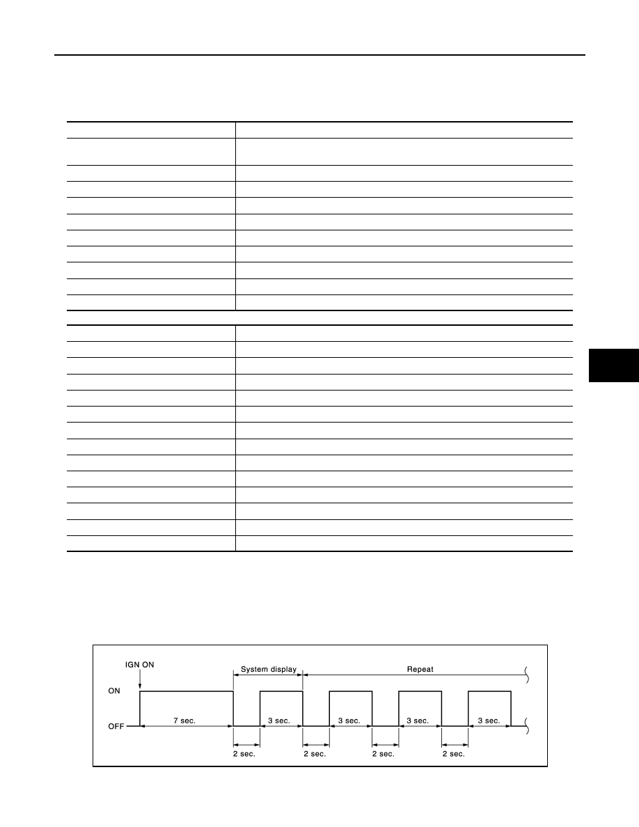
Turn ignition switch ON. Check the blinking pattern of air bag warning lamp.
There are 2 blinking patterns for the air bag warning lamp as per the following items. 
• Front air bag system: 3 second blink followed by a 0.5 second blink repeated.
• Side air bag system: Two 1.5 second blinks followed by a 0.5 second blink repeated.

Front air bag system

Side air bag system

How to Erase Self-diagnostic Result

After a malfunction is repaired, turn the ignition switch OFF for one second or more, then turn ignition switch
ON. The diagnosis mode returns to the user mode. At that time the self-diagnostic result is cleared.

EXAMPLE OF AIR BAG WARNING LAMP OPERATION IN THE DIAGNOSIS MODE

System Normal

When system is normal.

Single System Malfunction

• Front air bag system

Number of 0.5 second blinks

Malfunctioning items

0

• Self-diagnostic result is not erased after repair
• Intermittent malfunction is detected in the past

1

Seat belt pre-tensioner RH

2

Driver air bag module

3

Seat belt pre-tensioner LH

5

Occupant detction system control unit

6

Crash zone sensor

7

Air bag diagnosis sensor unit

8

Passenger air bag module

11

Passenger air bag OFF indicator

17

Air bag diagnosis sensor unit

Number of 0.5-second blinks

Malfunctioning items

1

Side air bag module RH

2

Side air bag module LH

3

Front satellite sensor RH

4

Front satellite sensor LH

5

Rear curtain air bag module RH

6

Rear curtain air bag module LH

7

Front curtain air bag module RH

8

Front curtain air bag module LH

9

Front door satellite sensor RH

10

Front door satellite sensor LH

11

Rear satellite sensor RH

12

Rear satellite sensor LH

20

Front door satellite sensor LH/RH

JMHIA0945GB

SRC-18

< SYSTEM DESCRIPTION >

DIAGNOSIS SYSTEM (AIR BAG)

When air bag diagnosis sensor unit system (Item display 1) is malfunctioning.

• Side air bag system

When rear curtain air bag module LH system (Item display 1) is malfunctioning.

Multiple Systems Malfunction

• Front air bag system

When driver air bag module (Item display 1) and air bag diagnosis sensor unit system (Item display 2) are
malfunctioning.

• Side air bag system

When front satellite sensor LH (Item display1) and rear curtain air bag module LH system (Item display 2)
are malfunctioning.

• Front air bag system and side air bag system

JMHIA1822GB

JMHIA1823GB

JMHIA1824GB

JMHIA1825GB

DIAGNOSIS SYSTEM (AIR BAG)

SRC-19

< SYSTEM DESCRIPTION >

C

D

E

F

G

I

J

K

L

M

A

B

SRC

N

O

P

When driver air bag module (Item display 1) and front satellite sensor RH (Item display2) are malfunctioning.

CONSULT Function

INFOID:0000000009649846

APPLICATION ITEM

CONSULT performs the following functions.

CAUSE OF WARNING LAMP

The SRS air bag warning lamp blinks when the ignition voltage is a voltage value (9V or less, or 16 V or more)
at which the SRS air bag cannot operate normally. After blinking, if the ignition voltage returns to normal, SRS
air bag warning lamp turns OFF.DTC memory is not performed while the abnormal ignition voltage is detected.
The mode cannot be switched to trouble diagnosis mode when the ignition switch is operated.“No DTC” is dis-
played when checking “Self-diagnosis result” using CONSULT.
NOTE:
• SRS air bag warning may blink when the condition is out of detection area* of the satellite sensor in door.

The system is normal if SRS air bag warning lamp turns OFF after the condition returns within detection area
of the satellite sensor in door.

• SRS air bag warning lamp blinks when the zero point reset is incomplete after replacing the occupant detec-

tion system control unit. (SRS air bag warning lamp turns OFF after the zero point reset is complete.)

• *: Pressure inside of door is excessively low and air bag system cannot be operated normally (example: alti-

tude is approximately 4,000 m or more).

JMHIA0950GB

Diagnosis mode

Description

Ecu Identification

Air bag diagnosis sensor unit ECU discriminated number (identification number) or part num-
ber is displayed. Air bag diagnosis sensor unit has individual ECU discriminated number 
(identification number) or part number based on model and equipment.

Self Diagnostic Result

The current self diagnosis results (also indicated with the number of air bag warning lamp 
blinks in the diagnosis mode) are displayed on CONSULT screen in real time. This refers to 
a malfunctioning part requiring repairs.
Refer to 

SRC-22, "DTC Index"

.

TROUBLE DIAG RECORD

With TROUBLE DIAG RECORD, diagnosis results previously erased by a reset operation 
can be displayed on CONSULT screen.

SELF-DIAG RESULT [CAN]

This item is displayed, but cannot be supported.

Cause of Warning Lamp

It displays the cause of warning lamp illumination that is not recorded in memory.

SRC-20

< SYSTEM DESCRIPTION >

DIAGNOSIS SYSTEM (AIR BAG)

Display item

Display content

Actions by worker

IGN VOLT COND

The ignition voltage recognized by air bag system (air bag 
control unit and occupant detection system control unit) is 
displayed or a message stating that condition is out of de-
tection range of satellite sensor in door is displayed.
• OK:  Normal
• LOW: The ignition voltage is low, high, or out of detec-

tion range of satellite sensor in door

Perform the check at an altitude of 4,000 m or 
less.
• Check battery voltage if the ignition voltage 

status is displayed as “LOW”.

• Check battery voltage if the ignition voltage 

status is“OK” and the number of times detect-
ed is 1 or more. This is because an ignition 
voltage error may be detected in the past.
NOTE:
If battery voltage is normal, the cause may be 
that out of detection range of satellite sensor 
in door is detected.

IGN VOLT TIME

Total number of times is displayed, summing up the num-
ber of times ignition voltage error is detected and the num-
ber of times that out of detection range of satellite sensor 
in door is detected.
(Detection record is erased and counter returns to “0” by 
“ERASE MEMORY” in “Self-diagnosis results” using CON-
SULT.)

LOW V RECORED

Number of times ignition switch ON is displayed after igni-
tion voltage error or out of detection range of satellite sen-
sor in door is detected.
(Detection record is erased and counter returns to “0” by 
“ERASE MEMORY” in “Self-diagnosis results” using CON-
SULT.)


Content   ..  1120  1121  1122  1123   ..