Nissan Quest E52. Manual - part 1104


  Index      Nissan     Nissan Quest E52 (2011-2014 year) - Service and Repair Manual


Search            


Content   ..  1102  1103  1104  1105   ..


Nissan Quest E52. Manual - part 1104


SEC-106

< DTC/CIRCUIT DIAGNOSIS >

[WITH INTELLIGENT KEY SYSTEM]

B20A0 CRANKING REQUEST CIRCUIT

B20A0 CRANKING REQUEST CIRCUIT

DTC Logic

INFOID:0000000009650773

DTC DETECTION LOGIC

NOTE:
If DTC B20A0 is displayed with DTC U1000, first perform the trouble diagnosis for DTC U1000. Refer to 

PCS-

30, "DTC Logic"

.

DTC CONFIRMATION PROCEDURE

1.

PERFORM DTC CONFIRMATION PROCEDURE

1.

Perform DTC CONFIRMATION PROCEDURE for DTC P1650. Refer to 

EC-374, "DTC Logic"

.

2.

Turn ignition switch ON.

3.

Check DTC in “Self Diagnostic Result” mode of “IPDM E/R” using CONSULT.

Is DTC detected?

YES

>> Refer to 

SEC-106, "Diagnosis Procedure"

.

NO

>> INSPECTION END

Diagnosis Procedure

INFOID:0000000009650774

1.

CHECK CRANKING REQUEST SIGNAL

1.

Turn ignition switch ON.

2.

Check voltage between IPDM E/R harness connector and ground under the following conditions.

Is the inspection result normal?

YES

>> GO TO 3.

NO

>> GO TO 2.

2.

CHECK CRANKING REQUEST SIGNAL CIRCUIT

1.

Turn ignition switch OFF.

2.

Disconnect IPDM E/R connector.

3.

Disconnect ECM connector.

4.

Check continuity between IPDM E/R harness connector and ECM harness connector.
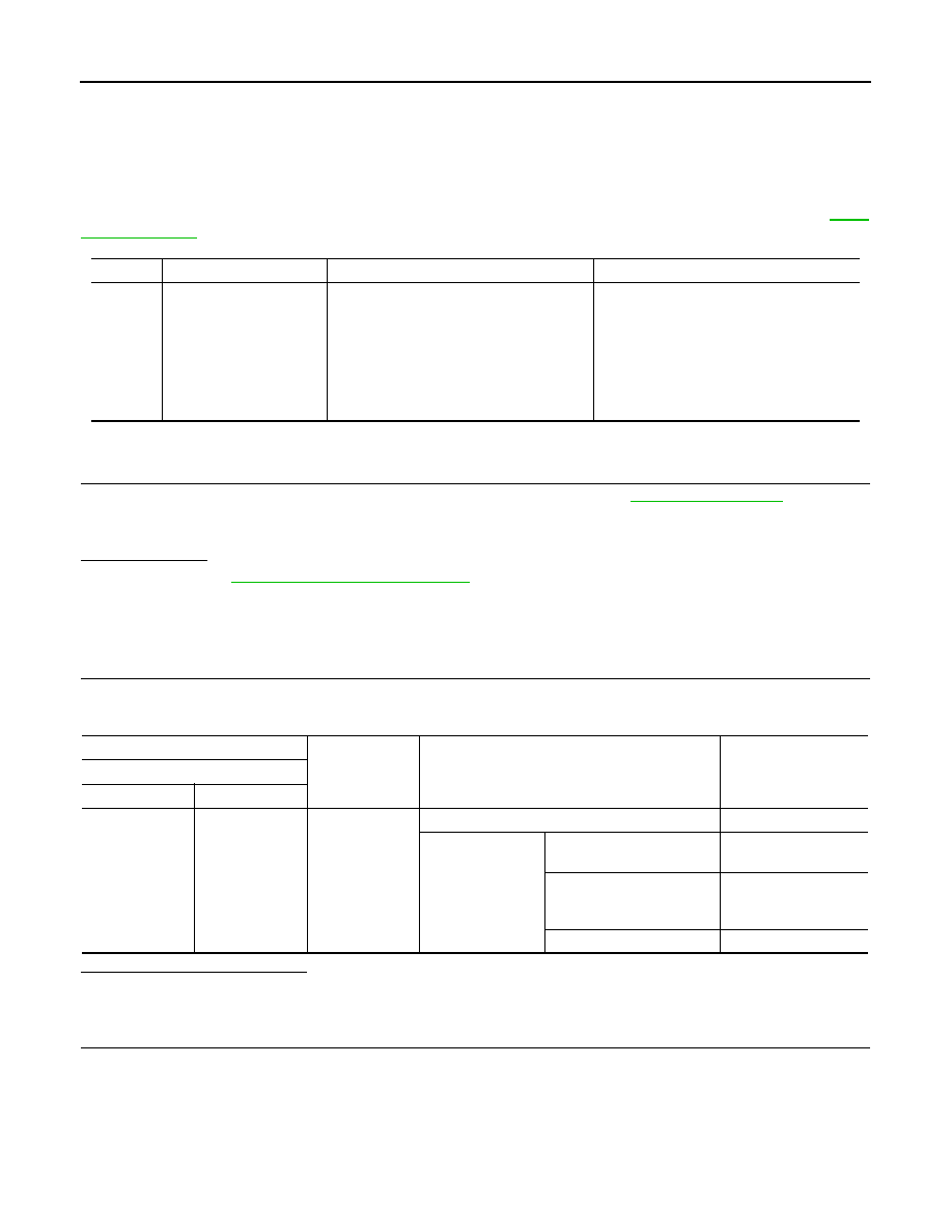
DTC No.

Trouble diagnosis name

DTC detecting condition

Possible cause

B20A0

STR CUT OFF SHORT 

When the following items do not match, a 
malfunction is detected.
• Cranking request signal from ECM
• Starter control relay control signal from 

ECM (CAN)

• Harness or connectors

(CAN communication line is open or 
shorted.)

• Harness or connectors

(Cranking request signal circuit is open or 
shorted.)

• IPDM  E/R
• ECM

(+)

(–)

Condition

Voltage (V)

(Approx.)

IPDM E/R

Connector

Terminal

F12

71

Ground

Ignition switch OFF

3.6

Ignition switch ON

• Engine: Stopped
• Selector lever position: P

0 - 1

• Engine: Stopped
• Selector lever position: 

Other than P

9 - 16

Engine running

9 - 16

B20A0 CRANKING REQUEST CIRCUIT

SEC-107

< DTC/CIRCUIT DIAGNOSIS >

[WITH INTELLIGENT KEY SYSTEM]

C

D

E

F

G

H

I

J

L

M

A

B

SEC

N

O

P

5.

Check continuity between BCM harness connector and ground.

Is the inspection result normal?

YES

>> GO TO 3.

NO

>> Repair or replace harness.

3.

REPLACE IPDM E/R

1.

Replace IPDM E/R. Refer to 

PCS-36, "Removal and Installation"

.

2.

Perform DTC CONFIRMATION PROCEDURE for DTC B20A0. Refer to 

SEC-106, "DTC Logic"

.

Is DTC detected?

YES

>> GO TO 4.

NO

>> INSPECTION END

4.

REPLACE ECM

Replace ECM.
Refer to 

EC-460, "Removal and Installation"

.

>> INSPECTION END

IPDM E/R

ECM

Continuity

Connector

Terminal

Connector

Terminal

F12

71

F7

8

Existed

IPDM E/R

Ground

Continuity

Connector

Terminal

F12

71

Not existed

SEC-108

< DTC/CIRCUIT DIAGNOSIS >

[WITH INTELLIGENT KEY SYSTEM]

B210B STARTER CONTROL RELAY

B210B STARTER CONTROL RELAY

DTC Logic

INFOID:0000000009650775

DTC DETECTION LOGIC

NOTE:
If DTC B210B is displayed with DTC U1000, first perform the trouble diagnosis for DTC U1000. Refer to 

PCS-

30, "DTC Logic"

.

DTC CONFIRMATION PROCEDURE

1.

PERFORM DTC CONFIRMATION PROCEDURE

1.

Press push-button ignition switch under the following conditions to start engine, and wait 1 second or
more.

-

Selector lever: In the P position

-

Brake pedal: Depressed

2.

Check DTC in “Self Diagnostic Result” mode of “IPDM E/R” using CONSULT.

Is DTC detected?

YES

>> Refer to 

SEC-108, "Diagnosis Procedure"

.

NO

>> INSPECTION END

Diagnosis Procedure

INFOID:0000000009650776

1.

CHECK SELF DIAGNOSTIC RESULT

Check DTC using CONSULT.
What is the display history of DTC “B210B”?

“CRNT”>> Replace IPDM E/R. Refer to 

PCS-36, "Removal and Installation"

.

“PAST” >> GO TO 2.

2.

CHECK INTERMITTENT INCIDENT

Refer to 

GI-42, "Intermittent Incident"

>> INSPECTION END

DTC No.

Trouble diagnosis name

DTC detecting condition

Possible cause

B210B

STR CONT RLY ON 
CIRC

When comparing the following items, IPDM E/R detects 
that starter control relay is stuck in the ON position for 
5 seconds or more.
• Starter control relay signal (CAN) from BCM
• Starter relay status signal (CAN) from BCM
• Starter control relay and starter relay status signal 

(IPDM E/R input)

• Starter control relay control signal (IPDM E/R output)
• P/N position signal input
• Ignition power supply No.2 signal from BCM

• Harness or connectors

(CAN communication line is 
open or shorted.
(Ignition power supply No.2 
circuit is open or shorted.)

• IPDM  E/R
• BCM

B210C STARTER CONTROL RELAY

SEC-109

< DTC/CIRCUIT DIAGNOSIS >

[WITH INTELLIGENT KEY SYSTEM]

C

D

E

F

G

H

I

J

L

M

A

B

SEC

N

O

P

B210C STARTER CONTROL RELAY

DTC Logic

INFOID:0000000009650777

DTC DETECTION LOGIC

NOTE:
• If DTC B210C is displayed with DTC U1000, first perform the trouble diagnosis for DTC U1000. Refer to

PCS-30, "DTC Logic"

.

• When IPDM E/R power supply voltage is low (Approx. 7 - 8 V for about 1 second), the DTC B210C may be

detected.

DTC CONFIRMATION PROCEDURE

1.

PERFORM DTC CONFIRMATION PROCEDURE

1.

Press push-button ignition switch to start engine, and wait 1 second or more.

2.

Check DTC in “Self Diagnostic Result” mode of “IPDM E/R” using CONSULT.

Is DTC detected?

YES

>> Refer to 

SEC-109, "Diagnosis Procedure"

.

NO

>> INSPECTION END

Diagnosis Procedure

INFOID:0000000009650778

1.

CHECK SELF DIAGNOSTIC RESULT

Check DTC in “Self Diagnostic Result” mode of “IPDM E/R” using CONSULT.
What is the display history of DTC “B210C”?

“CRNT”>> GO TO 3.
“PAST” >> GO TO 2.

2.

CHECK BATTERY VOLTAGE

Measure the battery voltage.

Which is the measurement result?

More than 12.4 V>>GO TO 5
Less than 12.4 V>>Perform battery inspection. Refer to 

PG-97, "How to Handle Battery"

.

3.

CHECK P/N POSITION SIGNAL CIRCUIT VOLTAGE

1.

Turn ignition switch ON

2.

Selector lever is in P position.

3.

Check the voltage between IPDM E/R harness connector and ground.

Is the inspection result normal?

DTC No.

Trouble diagnosis name

DTC detecting condition

Possible cause

B210C

STR CONT RLY OFF CIRC

When comparing the following items, IPDM E/R 
detects that starter control relay is stuck in the 
OFF position for 5 seconds or more.
• Starter control relay signal (CAN) from BCM
• Starter relay status signal (CAN) from BCM
• Starter control relay and starter relay status 

signal (IPDM E/R input)

• Starter control relay control signal (IPDM E/R 

output)

• P/N position signal input
• Ignition power supply No.2 signal from BCM

• Harness or connectors

(CAN communication line is 
open or shorted.
(Ignition power supply No.2 
circuit is open or shorted.)

• IPDM E/R
• BCM

(+)

(-)

Voltage

(Approx.)

IPDM E/R

Connector

Terminal

E11

46

Ground

Battery voltage


Content   ..  1102  1103  1104  1105   ..