Content .. 1057 1058 1059 1060 ..
Nissan Quest E52. Manual - part 1059
POWER RETURN MOTOR
SE-65
< DTC/CIRCUIT DIAGNOSIS >
C
D
E
F
G
H
I
K
L
M
A
B
SE
N
O
P
POWER RETURN MOTOR
LH
LH : Diagnosis Procedure
INFOID:0000000009652965
1.
CHECK POWER RETURN MOTOR (LH) INPUT SIGNAL
1.
Turn ignition switch OFF.
2.
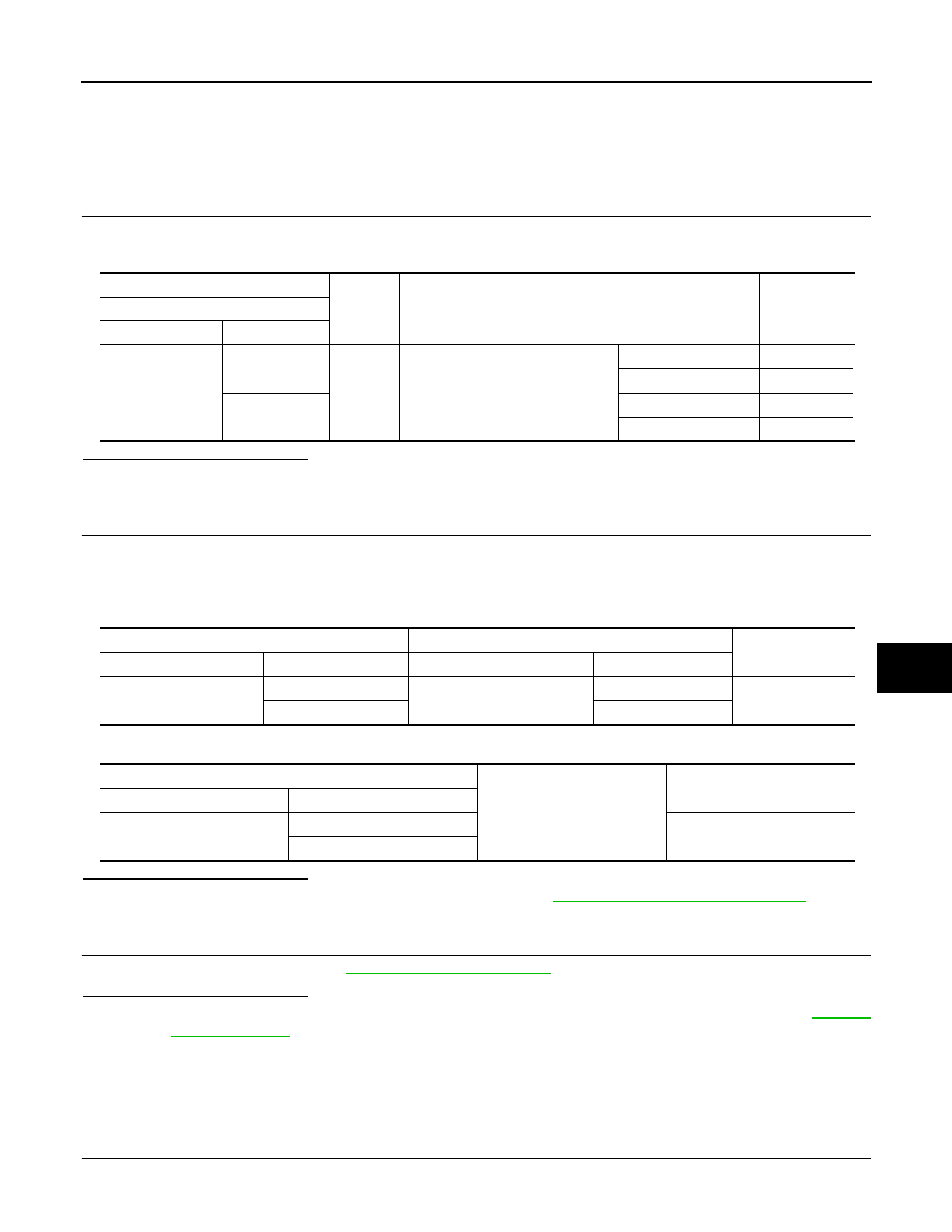
Check voltage between power return motor assembly (LH) harness connector and ground.
Is the inspection result normal?
YES
>> GO TO 3.
NO
>> GO TO 2.
2.
CHECK POWER RETURN MOTOR (LH) CIRCUIT
1.
Disconnect seatback power return control unit connector and power return motor assembly (LH) connec-
tor.
2.
Check continuity between seatback power return control unit harness connector and power return motor
assembly (LH) harness connector.
3.
Check continuity between seatback power return control unit harness connector and ground.
Is the inspection result normal?
YES
>> Replace seatback power return control unit. Refer to
SE-139, "Removal and Installation"
NO
>> Repair or replace harness.
3.
CHECK INTERMITTENT INCIDENT
Check intermittent incident. Refer to
GI-42, "Intermittent Incident"
.
Is the inspection result normal?
YES
>> Replace power return motor assembly (LH) [reclining device assembly (LH)]. Refer to
NO
>> Repair or replace harness.
RH
RH : Diagnosis Procedure
INFOID:0000000009652966
1.
CHECK POWER RETURN MOTOR (RH) INPUT SIGNAL
1.
Turn ignition switch OFF.
(+)
(–)
Condition
Voltage (V)
Power return motor assembly (LH)
Connector
Terminal
B498
1
Ground
Power return motor assembly (LH)
Reverse operation
9 – 16
Other than the above
0 – 0.5
5
Return operation
9 – 16
Other than the above
0 – 0.5
Seatback power return control unit
Power return motor assembly (LH)
Continuity
Connector
Terminal
Connector
Terminal
B487
5
B498
1
Existed
6
5
Seatback power return control unit
Ground
Continuity
Connector
Terminal
B487
5
Not existed
6