Nissan Quest E52. Manual - part 82
AV
U1243 FRONT DISPLAY UNIT
AV-207
< DTC/CIRCUIT DIAGNOSIS >
[BASE AUDIO WITH SEPARATE DISPLAY]
C
D
E
F
G
H
I
J
K
L
M
B
A
O
P
U1243 FRONT DISPLAY UNIT
DTC Logic
INFOID:0000000009652035
Diagnosis Procedure
INFOID:0000000009652036
1.
CHECK FRONT DISPLAY UNIT POWER SUPPLY AND GROUND CIRCUITS
Check front display unit power supply and ground circuits. Refer to
AV-213, "FRONT DISPLAY UNIT : Diagno-
Is inspection result normal?
YES
>> GO TO 2.
NO
>> Repair malfunctioning parts.
2.
CHECK CONTINUITY COMMUNICATION CIRCUITS
1.
Turn ignition switch OFF.
2.
Disconnect front display unit connector and AV control unit connector.
3.
Check continuity between front display unit harness connector and AV control unit harness connector.
4.
Check continuity between front display unit harness connector and ground.
Is inspection result normal?
YES
>> GO TO 3.
NO
>> Repair harness or connector.
3.
CHECK COMMUNICATION SIGNAL
1.
Connect front display unit connector and AV control unit connector.
2.
Turn ignition switch ON.
3.
Check signal between front display unit harness connector and ground.
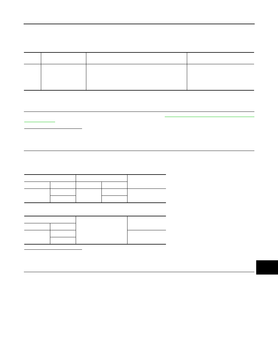
DTC
Display contents of
CONSULT
DTC detection condition
Possible malfunction factor
U1243
FRONT DISP CONN
[U1243]
When either one of the following items are detected:
• front display unit power supply and ground circuits are
malfunctioning.
• serial communication circuits between front display unit
and AV control unit are malfunctioning.
• Front display unit power supply and
ground circuits.
• Serial communication circuits be-
tween front display unit and AV
control unit.
Front display unit
AV control unit
Continuity
Connector
Terminals
Connector
Terminals
M156
11
M172
51
Existed
22
39
Front display unit
Ground
Continuity
Connector
Terminals
M156
11
Not existed
12