Nissan Quest E52. Manual - part 73
AV
FRONT DISPLAY UNIT
AV-171
< ECU DIAGNOSIS INFORMATION >
[BASE AUDIO WITH SEPARATE DISPLAY]
C
D
E
F
G
H
I
J
K
L
M
B
A
O
P
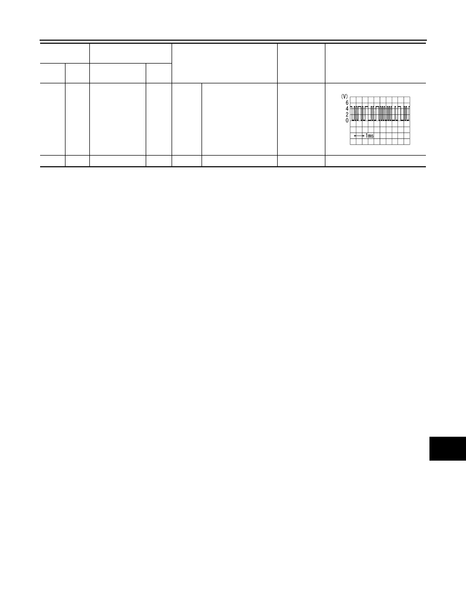
22
(R)
1
(B)
Communication
signal
(DISP
→
CONT)
Output
Ignition
switch
ON
When adjusting display
brightness.
Waveform of
0.5 V or less –
3.5 V or more
is output.
23
—
Shield
—
—
—
—
—
Terminal
(Wire color)
Description
Condition
Standard
Reference value
(Approx.)
+
–
Signal name
Input/
Output
PKIB5039J