Nissan Quest E52. Manual - part 67
AV
DIAGNOSIS SYSTEM (AV CONTROL UNIT)
AV-147
< SYSTEM DESCRIPTION >
[BASE AUDIO WITH SEPARATE DISPLAY]
C
D
E
F
G
H
I
J
K
L
M
B
A
O
P
DIAGNOSIS SYSTEM (AV CONTROL UNIT)
Description
INFOID:0000000009652009
• The AV control unit diagnosis function starts up with multifunction switch operation and the AV control unit
performs a diagnosis for each unit in the system during the on board diagnosis.
• Perform a CONSULT diagnosis if the on board diagnosis does not start, e.g., the screen does not display
anything, the multifunction switch does not function, etc.
On Board Diagnosis Function
INFOID:0000000009652010
MULTIFUNCTION SWITCH AND PRESET SWITCH SELF-DIAGNOSIS FUNCTION
The ON/OFF operation (continuity) of each switch in the multifunction switch and preset switch can be
checked.
Self-diagnosis Mode
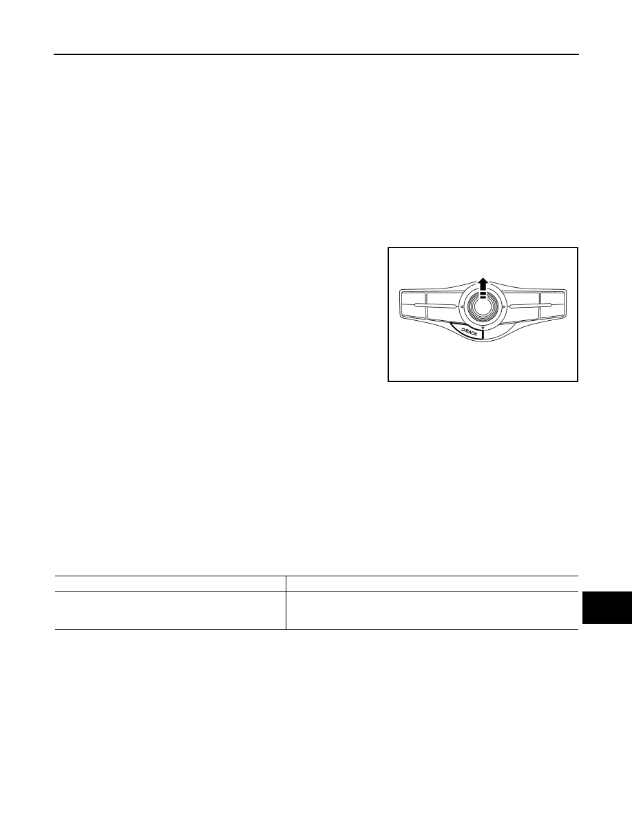
•
Press the “BACK” switch and the “UP” switch of the 4-direction
switches within 10 seconds after turning the ignition switch from
OFF to ACC and hold them for 3 seconds or more. Then the
buzzer sounds, all indicators of the preset switch illuminate, and
the self-diagnosis mode starts.
• The continuity of each switch at the ON position can be checked
by pressing the switch. The buzzer sounds if the switch is normal.
NOTE:
The disk eject switch cannot be checked.
Finishing Self-diagnosis Mode
Self-diagnosis mode is canceled when turning the ignition switch OFF.
ON BOARD DIAGNOSIS
Description
• The trouble diagnosis function has a self-diagnosis mode for conducting trouble diagnosis automatically and
a confirmation/adjustment mode for operating manually.
• Self-diagnosis mode performs the AV control unit diagnosis and the connection diagnosis between each of
the units that make up the system, and it indicates the results to the front display unit.
• The confirmation/adjustment mode allows the technician to check, modify or adjust the vehicle signals and
set values, as well as to monitor the system error records and system communication status. The checking,
modifying or adjusting generally require human intervention and judgment (the system cannot make judg-
ment automatically).
On Board Diagnosis Item
JSNIA4238ZZ
Mode
Description
Self Diagnosis
• AV control unit diagnosis.
• Diagnoses the connections across system components, between AV
control unit and each unit.