Nissan Cube. Manual - part 921


  Index      Nissan     Nissan Cube (2014 year) - Service and Repair Manual


Search            


Content   ..  919  920  921  922   ..


Nissan Cube. Manual - part 921


COMPONENT PARTS

STC-5

< SYSTEM DESCRIPTION >

C

D

E

F

H

I

J

K

L

M

A

B

STC

N

O

P

SYSTEM DESCRIPTION

COMPONENT PARTS

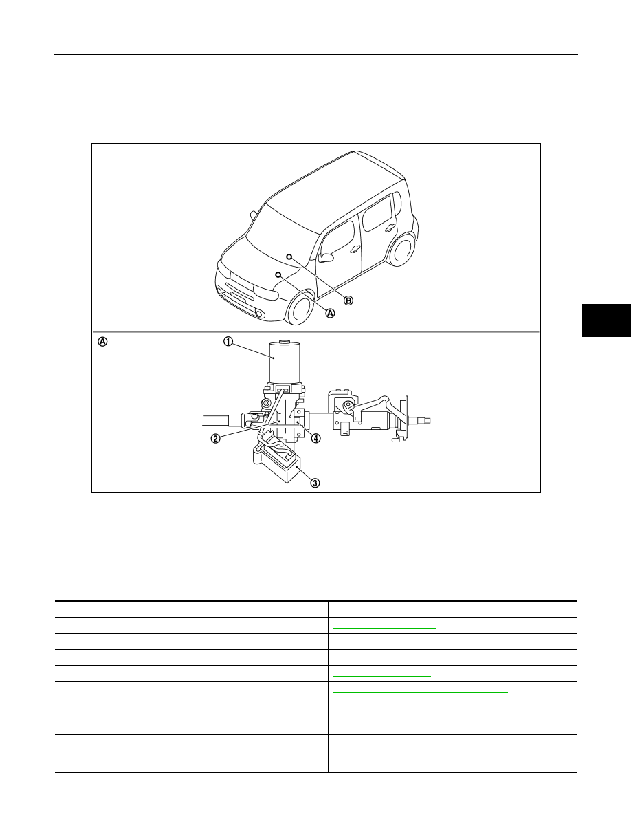
Component Parts Location

INFOID:0000000009945953

Component Description

INFOID:0000000009945954

1.

EPS motor

2.

Reduction gear

3.

EPS control unit

4.

Torque sensor

A.

Steering column assembly

B.

EPS warning lamp
(Combination meter)

JSGIA0662ZZ

Components parts

Reference

EPS control unit

STC-6, "EPS Control Unit"

EPS motor

STC-6, "EPS Motor"

Torque sensor

STC-6, "Torque Sensor"

Reduction gear

STC-6, "Reduction Gear"

EPS warning lamp

STC-7, "EPS SYSTEM : System Description"

ECM

• Transmits mainly the following signals to EPS control unit via 

CAN communication. 

- Engine status signal 

ABS actuator and electric unit (control unit)

• Transmits mainly the following signal to EPS control unit via 

CAN communication. 

- Vehicle speed signal (ABS)

STC-6

< SYSTEM DESCRIPTION >

COMPONENT PARTS

EPS Control Unit

INFOID:0000000009945955

• EPS control unit performs an arithmetical operation on data, such as steering wheel turning force (sensor

signal) from the torque sensor, vehicle speed signal, etc. Then it generates an optimum assist torque signal
to the EPS motor according to the driving condition.

• EPS control unit decreases the output signal to EPS motor while extremely using the power steering func-

tion (e.g., full steering) consecutively for protecting EPS motor and EPS control unit (Overload protection
control).

EPS Motor

INFOID:0000000009945956

EPS motor provides the assist torque by the control signal from EPS control unit.

Torque Sensor

INFOID:0000000009945957

Torque sensor detects the steering torque, and transmit the signal to EPS control unit.

Reduction Gear

INFOID:0000000009945958

Reduction gear increases the assist torque provided from EPS motor with worm gears, and outputs to the col-
umn shaft.

Combination meter

• Transmits mainly the following signal to EPS control unit via 

CAN communication. 

- Vehicle speed signal (Meter)

• Turns ON the EPS warning lamp according to the signal from 

EPS control unit via CAN communication.

Components parts

Reference

SYSTEM

STC-7

< SYSTEM DESCRIPTION >

C

D

E

F

H

I

J

K

L

M

A

B

STC

N

O

P

SYSTEM

EPS SYSTEM

EPS SYSTEM : System Description

INFOID:0000000009945959

• EPS control unit performs an arithmetical operation on data, such

as steering wheel turning force (sensor signal) from the torque
sensor, vehicle speed signal, etc. Then it generates an optimum
assist torque signal to the EPS motor according to the driving con-
dition.

• In case of an error in the electrical system, the fail-safe function

stops output signals to the EPS motor. Refer to 

STC-12, "Fail-

Safe"

.

• EPS control unit decreases the output signal to EPS motor while

extremely using the power steering function (e.g., full steering)
consecutively for protecting EPS motor and EPS control unit
(Overload protection control). Refer to 

STC-13, "Protection Func-

tion"

.

• Extensive steering at low speed will cause the EPS control unit

and EPS motor to heat up, once temperature reaches critical point
EPS control unit will reduce current to reduce heat up. System will
recover as temperature lowers (reduced or no assistance).

SYSTEM DIAGRAM

INPUT/OUTPUT SIGNAL

Communicates the signal from each control unit via CAN communication. 

JSGIA1102GB

JSGIA0877GB

Control unit

Signal status

ECM

• Transmits mainly the following signals to EPS control unit via CAN communication. 
- Engine status signal 

ABS actuator and electric unit (con-
trol unit)

• Transmits mainly the following signals to EPS control unit via CAN communication. 
- Vehicle speed signal (ABS)

Combination meter

• Transmits mainly the following signals to EPS control unit via CAN communication. 
- Vehicle speed signal (Meter)
• Receives mainly the following signals from EPS control unit via CAN communication. 
- EPS warning lamp signal 

STC-8

< SYSTEM DESCRIPTION >

SYSTEM

EPS WARNING LAMP INDICATION

• Turn ON when there is a malfunction in EPS system. If indicates that fail-safe mode is engaged and enters a

manual steering state (Control turning force steering wheel becomes heavy).

• Also turns ON when ignition switch is turned ON, for purpose of lamp check. Turns OFF after the engine

starts, if system is normal.

CAUTION:

EPS warning lamp also turns ON due to data reception error, CAN communication error etc.

EPS SYSTEM : Fail-Safe

INFOID:0000000009945960

• If any malfunction occurs in the system and control unit detects the malfunction, EPS warning lamp on com-

bination meter turns ON to indicate system malfunction.

• When EPS warning lamp is ON, the system enters into a manual steering state. (Control turning force steer-

ing wheel becomes heavy.)

• Under abnormal vehicle speed signal conditions, vehicle speed is judged as constant.

EPS SYSTEM : Protection Function

INFOID:0000000009945961

EPS control unit decreases the output signal to EPS motor while extremely using the power steering function
(e.g., full steering) consecutively for protecting EPS motor and EPS control unit (Overload protection control).
While activating overload protection control, the assist torque gradually decreases, and the steering wheel
turning force becomes heavy. The normal assist torque is recovered if the steering wheel is not turned for a
while.

Condition

EPS warning lamp

Ignition switch ON. (Lamp check)

ON

Engine running.

OFF

EPS system malfunction [Other diagnostic item]

ON


Content   ..  919  920  921  922   ..