Nissan Cube. Manual - part 753
POWER WINDOW SYSTEM
PWC-9
< SYSTEM DESCRIPTION >
C
D
E
F
G
H
I
J
L
M
A
B
PWC
N
O
P
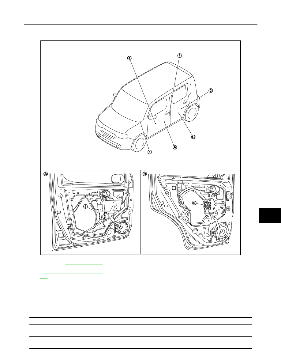
Component Parts Location
INFOID:0000000009950851
Component Description
INFOID:0000000009950852
JMKIA3996ZZ
1.
BCM Refer to
(With Intelligent Key)
or
BCS-95, "Component Parts Loca-
(Without Intelligent Key)
2.
Rear power window switch LH
3.
Front door switch (driver side)
4.
Power window main switch
5.
Front power window motor (driver side)
6.
Rear power window motor LH
A.
View with front door finisher re-
moved.
B.
View with rear door finisher removed.
Component parts
Description
BCM
• Supplies power supply to power window switch.
• Controls retained power.
Power window main switch
• Directly controls all power window motor of all doors.
• Controls anti-pinch operation of power window.