Nissan Cube. Manual - part 750


  Index      Nissan     Nissan Cube (2014 year) - Service and Repair Manual


Search            


Content   ..  748  749  750  751   ..


Nissan Cube. Manual - part 750


PG

PREPARATION

PG-81

< PREPARATION >

[POWER SUPPLY & GROUND CIRCUIT]

C

D

E

F

G

H

I

J

K

L

B

A

O

P

N

PREPARATION

PREPARATION

Special Service Tools

INFOID:0000000009945606

Tool number
(Kent-Moore No.)
Tool name

Description


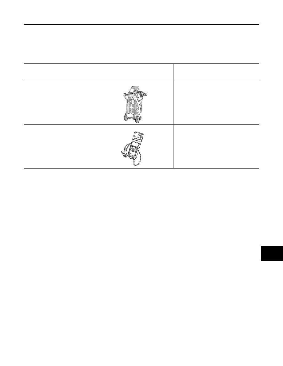
(—) Model GR8-1200 NI
Multitasking battery and electrical di-
agnostic station

Tests batteries, starting and charging sys-
tems and charges batteries.
For operating instructions, refer to diagnostic 
station instruction manual.


(—) Model EXP-800 NI
Battery and electrical diagnostic ana-
lyzer

Tests batteries and charging systems.
For operating instructions, refer to diagnostic 
analyzer instruction manual.

AWIIA1239ZZ

JSMIA0806ZZ

PG-82

< REMOVAL AND INSTALLATION >

[POWER SUPPLY & GROUND CIRCUIT]

BATTERY

REMOVAL AND INSTALLATION

BATTERY

Exploded View

INFOID:0000000009945607

Removal and Installation

INFOID:0000000009945608

REMOVAL

1.

Remove resonator.

2.

Remove cover of battery positive terminal.

3.

Loosen battery terminal nuts (1), and disconnect both battery
cables from battery terminals. 

CAUTION:

When disconnecting, disconnect the battery cable from the
negative terminal first.

4.

Remove battery fix frame mounting nuts (2) and battery fix
frame (3).

5.

Remove battery.

INSTALLATION

Install in the reverse order of removal.

CAUTION:

When connecting, connect the battery cable to the positive terminal first.
Reset electronic systems as necessary. Refer to 

GI-53, "ADDITIONAL SERVICE WHEN REMOVING BAT-

TERY NEGATIVE TERMINAL : Required Procedure After Battery Disconnection"

.

1

: Battery fix frame

Refer to 

GI-4, "Components"

 for symbols in the figure.

JPMIA1399GB

JPMIA1470ZZ

PG

BATTERY TERMINAL WITH FUSIBLE LINK

PG-83

< REMOVAL AND INSTALLATION >

[POWER SUPPLY & GROUND CIRCUIT]

C

D

E

F

G

H

I

J

K

L

B

A

O

P

N

BATTERY TERMINAL WITH FUSIBLE LINK

Exploded View

INFOID:0000000009945609

Removal and Installation

INFOID:0000000009945610

REMOVAL

1.

Disconnect the battery cable from the negative terminal.

2.

Remove cover of battery positive terminal.

3.

Remove harness mounting nut (1) and fusible link holder mount-
ing nut (2).

4.

Disconnect harness connector (3) and remove battery terminal
with fusible link (4).

INSTALLATION

Install in the reverse order of removal.

1

: Battery terminal with fusible link

2

: Harness connector

Refer to 

GI-4, "Components"

 for symbols in the figure.

JPMIA1513GB

JPMIA1471ZZ

PG-84

< SERVICE DATA AND SPECIFICATIONS (SDS) 

[POWER SUPPLY & GROUND CIRCUIT]

SERVICE DATA AND SPECIFICATIONS (SDS)

SERVICE DATA AND SPECIFICATIONS (SDS)

SERVICE DATA AND SPECIFICATIONS (SDS)

Battery

INFOID:0000000009945611

Type

55D23L

20 hour rate capacity

[V – Ah]

12 – 60

Cold cranking current (For reference value)

[A]

356


Content   ..  748  749  750  751   ..