Nissan Cube. Manual - part 549


  Index      Nissan     Nissan Cube (2014 year) - Service and Repair Manual


Search            


Content   ..  547  548  549  550   ..


Nissan Cube. Manual - part 549


HAC-34

< DTC/CIRCUIT DIAGNOSIS >

[AUTOMATIC AIR CONDITIONING]

AMBIENT SENSOR

Is the inspection result normal?

YES

>> GO TO 3.

NO

>> Repair the harnesses or connectors.

3.

CHECK AMBIENT SENSOR

Check the ambient sensor components. Refer to 

HAC-34, "Component Inspection"

Is the inspection result normal?

YES

>> INSPECTION END

NO

>> Replace the ambient sensor. 

4.

CHECK AMBIENT SENSOR OPEN CIRCUIT

1.

Turn the ignition switch OFF.

2.

Disconnect the A/C auto amp. connector. 

3.

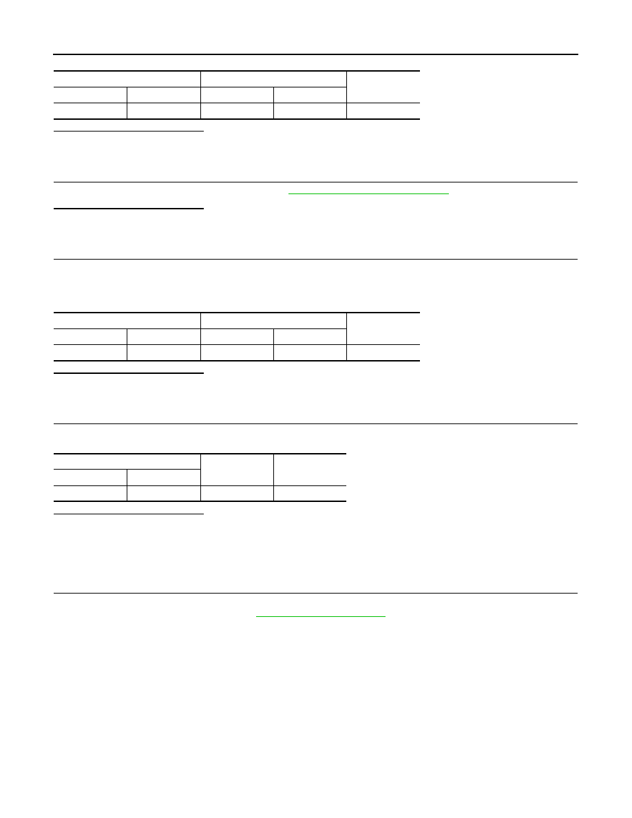
Check continuity between ambient sensor harness connector and A/C auto amp. harness connector. 

Is the inspection result normal?

YES

>> GO TO 5.

NO

>> Repair the harnesses or connectors.

5.

CHECK AMBIENT SENSOR SHORT CIRCUIT

Check continuity between ambient sensor harness connector and the ground. 

Is the inspection result normal?

YES

>> Replace the A/C auto amp.

NO

>> Repair the harnesses or connectors.

Component Inspection

INFOID:0000000009950981

1.

CHECK AMBIENT SENSOR

1.

Turn the ignition switch OFF.

2.

Remove the ambient sensor. Refer to 

HAC-123, "Exploded View"

3.

Check the resistance between the ambient sensor terminals. Refer to the applicable table for the normal
value. 

Ambient sensor

A/C auto amp.

Continuity

Connector

Terminal

Connector

Terminal

E53

2

M50

6

Existed

Ambient sensor

A/C auto amp.

Continuity

Connector

Terminal

Connector

Terminal

E53

1

M51

22

Existed

Ambient sensor

Continuity

Connector

Terminal

E53

1

Ground

Not existed

AMBIENT SENSOR

HAC-35

< DTC/CIRCUIT DIAGNOSIS >

[AUTOMATIC AIR CONDITIONING]

C

D

E

F

G

H

J

K

L

M

A

B

HAC

N

O

P

Is the inspection result normal?

YES

>> INSPECTION END

NO

>> Replace the ambient sensor. 

Terminal

Condition

Resistance: k

Temperature: 

°

C (

°

F) 

1

2

15 (5)

12.73

10 (14)

9.92

5 (23)

7.80

0 (32) 

6.19

5 (41) 

4.95

10 (50)

3.99

15 (59)

3.24

20 (68)

2.65

25 (77)

2.19

30 (86)

1.81

35 (95)

1.51

40 (104)

1.27

45 (113)

1.07

HAC-36

< DTC/CIRCUIT DIAGNOSIS >

[AUTOMATIC AIR CONDITIONING]

IN-VEHICLE SENSOR

IN-VEHICLE SENSOR

Description

INFOID:0000000009950982

COMPONENT DESCRIPTION

• The in-vehicle sensor (1) is installed to the finisher. 
• The in-vehicle sensor converts the interior air temperature of the

passenger room sucked by the aspirator detected with the ther-
mistor into the voltage, and the A/C auto amp. inputs this voltage. 

ASPIRATOR

The aspirator (1) generates the vacuum by the air blown from the A/
C unit assembly and draws the air of the passenger room to the in-
vehicle sensor area via the aspirator duct. 

INTERIOR AIR TEMPERATURE CORRECTION

• The A/C auto amp. inputs the temperature detected with the in-vehicle sensor as the interior air temperature. 
• Perform the correction of the temperature detected with the in-vehicle sensor for each air conditioner control. 

Diagnosis Procedure

INFOID:0000000009950983

1.

CHECK IN-VEHICLE SENSOR POWER SUPPLY CIRCUIT

1.

Turn the ignition switch OFF.

2.

Disconnect the in-vehicle sensor connector. 

3.

Turn the ignition switch ON.

4.

Check voltage between in-vehicle sensor harness connector and the ground. 

JPIIA1744ZZ

: Vehicle front

JPIIA1745ZZ

RJIA1804E

(+)

(

)

Voltage

(Approx.)

In-vehicle sensor

Connector

Terminal

M41

1

Ground

5 V

IN-VEHICLE SENSOR

HAC-37

< DTC/CIRCUIT DIAGNOSIS >

[AUTOMATIC AIR CONDITIONING]

C

D

E

F

G

H

J

K

L

M

A

B

HAC

N

O

P

Is the inspection result normal?

YES

>> GO TO 2.

NO

>> GO TO 4.

2.

CHECK IN-VEHICLE SENSOR GROUND CIRCUIT CONTINUITY

1.

Turn the ignition switch OFF.

2.

Disconnect the A/C auto amp. connector. 

3.

Check continuity between in-vehicle sensor harness connector and A/C auto amp. harness connector. 

Is the inspection result normal?

YES

>> GO TO 3.

NO

>> Repair the harnesses or connectors.

3.

CHECK IN-VEHICLE SENSOR

Check the in-vehicle sensor components. Refer to 

HAC-37, "Component Inspection"

Is the inspection result normal?

YES

>> INSPECTION END

NO

>> Replace the in-vehicle sensor. 

4.

CHECK IN-VEHICLE SENSOR OPEN CIRCUIT

1.

Turn the ignition switch OFF.

2.

Disconnect the A/C auto amp. connector. 

3.

Check continuity between in-vehicle sensor harness connector and A/C auto amp. harness connector. 

Is the inspection result normal?

YES

>> GO TO 5.

NO

>> Repair the harnesses or connectors.

5.

CHECK IN-VEHICLE SENSOR SHORT CIRCUIT

Check continuity between in-vehicle sensor harness connector and the ground. 

Is the inspection result normal?

YES

>> Replace the A/C auto amp. 

NO

>> Repair the harnesses or connectors.

Component Inspection

INFOID:0000000009950984

1.

CHECK IN-VEHICLE SENSOR

1.

Turn the ignition switch OFF.

2.

Remove the in-vehicle sensor. Refer to 

HAC-124, "Exploded View"

3.

Check the resistance between the in-vehicle sensor terminals. Refer to the applicable table for the normal
value. 

In-vehicle sensor

A/C auto amp.

Continuity

Connector

Terminal

Connector

Terminal

M41

2

M50

6

Existed

In-vehicle sensor

A/C auto amp.

Continuity

Connector

Terminal

Connector

Terminal

M41

1

M51

24

Existed

In-vehicle sensor

Continuity

Connector

Terminal

M41

1

Ground

Not existed


Content   ..  547  548  549  550   ..