Nissan Cube. Manual - part 514


  Index      Nissan     Nissan Cube (2014 year) - Service and Repair Manual


Search            


Content   ..  512  513  514  515   ..


Nissan Cube. Manual - part 514


GI-24

< VEHICLE INFORMATION >

IDENTIFICATION INFORMATION

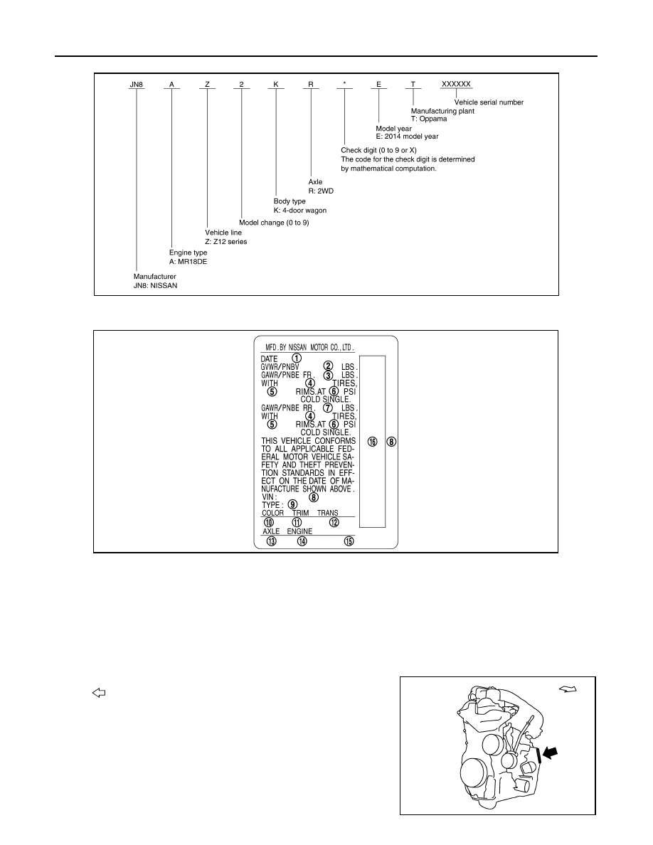
VEHICLE IDENTIFICATION NUMBER ARRANGEMENT

CERTIFICATION LABEL 

ENGINE SERIAL NUMBER 

JSAIA3274GB

1.

MFR Month / Year

2.

Gross vehicle weight rating

3.

Gross axle weight rating (Front)

4.

Tire size

5.

Wheel size

6.

Tire inflation pressure

7.

Gross axle weight rating (Rear)

8.

Vehicle identification number

9.

Verification model code

10. Body color number

11.

Trim color number

12. Transmission type

13. Axle type

14. Engine type

15. Engine displacement

16. VIN bar code

JSAIA2499ZZ

: Vehicle front

SAIA1341E

IDENTIFICATION INFORMATION

GI-25

< VEHICLE INFORMATION >

C

D

E

F

G

H

I

J

K

L

M

B

GI

N

O

P

CVT NUMBER 

MANUAL TRANSAXLE NUMBER

Dimensions

INFOID:0000000009947040

Unit: mm (in)

*1: With front license plate bracket

*2: Without front license plate bracket

Wheels & Tires

INFOID:0000000009947041

: Vehicle front

JPAIA0448ZZ

: Vehicle front

SAIA1338E

Overall length

3,980 (156.7)

*1

3,975 (156.5)

*2

Overall width

1,695 (66.7)

Overall height

1,680 (66.1)

Front tread

1,475 (58.1)

Rear tread

1,480 (58.3)

Wheelbase

2,530 (99.6)

Conventional

15 inch

Tire

P195/60R15 87H

Road wheel
(Steel)

Size

15 

×

 6J

Inset

42 mm (1.65 in)

16 inch

Tire

P195/55R16 86V

Road wheel
(Aluminum)

Size

16 

×

 6J

Inset

42 mm (1.65 in)

Spare

15 inch

Tire

T125/70D15 95M

Road wheel
(Steel)

Size

15 

×

 4T

Inset

35 mm (1.38 in)

GI-26

< PRECAUTION >

PRECAUTIONS

PRECAUTION

PRECAUTIONS

Description

INFOID:0000000009947042

Observe the following precautions to ensure safe and proper servicing. These precautions are not
described in each individual section.

Precaution for Supplemental Restraint System (SRS) "AIR BAG" and "SEAT BELT 
PRE-TENSIONER"

INFOID:0000000009947043

The Supplemental Restraint System such as “AIR BAG” and “SEAT BELT PRE-TENSIONER”, used along
with a front seat belt, helps to reduce the risk or severity of injury to the driver and front passenger for certain
types of collision. This system includes seat belt switch inputs and dual stage front air bag modules. The SRS
system uses the seat belt switches to determine the front air bag deployment, and may only deploy one front
air bag, depending on the severity of a collision and whether the front occupants are belted or unbelted.
Information necessary to service the system safely is included in the “SRS AIR BAG” and “SEAT BELT” of this
Service Manual.

WARNING:

Always observe the following items for preventing accidental activation.
• To avoid rendering the SRS inoperative, which could increase the risk of personal injury or death in

the event of a collision that would result in air bag inflation, all maintenance must be performed by
an authorized NISSAN/INFINITI dealer.

• Improper maintenance, including incorrect removal and installation of the SRS, can lead to personal

injury caused by unintentional activation of the system. For removal of Spiral Cable and Air Bag
Module, see “SRS AIR BAG”.

• Never use electrical test equipment on any circuit related to the SRS unless instructed to in this Ser-

vice Manual. SRS wiring harnesses can be identified by yellow and/or orange harnesses or harness
connectors.

PRECAUTIONS WHEN USING POWER TOOLS (AIR OR ELECTRIC) AND HAMMERS

WARNING:

Always observe the following items for preventing accidental activation.
• When working near the Air Bag Diagnosis Sensor Unit or other Air Bag System sensors with the

ignition ON or engine running, never use air or electric power tools or strike near the sensor(s) with
a hammer. Heavy vibration could activate the sensor(s) and deploy the air bag(s), possibly causing
serious injury.

• When using air or electric power tools or hammers, always switch the ignition OFF, disconnect the

battery, and wait at least 3 minutes before performing any service.

Precaution for Procedure without Cowl Top Cover

INFOID:0000000009947044

When performing the procedure after removing cowl top cover, cover
the lower end of windshield with urethane, etc to prevent damage to
windshield.

PIIB3706J

PRECAUTIONS

GI-27

< PRECAUTION >

C

D

E

F

G

H

I

J

K

L

M

B

GI

N

O

P

Precautions for Removing of Battery Terminal

INFOID:0000000010076503

•  When removing the 12V battery terminal, turn OFF the ignition

switch and wait at least 30 seconds.
NOTE:
ECU may be active for several tens of seconds after the ignition
switch is turned OFF. If the battery terminal is removed before ECU
stops, then a DTC detection error or ECU data corruption may
occur.

•  For vehicles with the 2-batteries, be sure to connect the main bat-

tery and the sub battery before turning ON the ignition switch.
NOTE:
If the ignition switch is turned ON with any one of the terminals of
main battery and sub battery disconnected, then DTC may be
detected.

•  After installing the 12V battery, always check "Self Diagnosis Result" of all ECUs and erase DTC.

NOTE:
The removal of 12V battery may cause a DTC detection error.

General Precautions

INFOID:0000000009947045

• Do not operate the engine for an extended period of time without

proper exhaust ventilation.
Keep the work area well ventilated and free of any inflammable
materials. Special care should be taken when handling any inflam-
mable or poisonous materials, such as gasoline, refrigerant gas,
etc. When working in a pit or other enclosed area, be sure to prop-
erly ventilate the area before working with hazardous materials.
Do not smoke while working on the vehicle.

• Before jacking up the vehicle, apply wheel chocks or other tire

blocks to the wheels to prevent the vehicle from moving. After jack-
ing up the vehicle, support the vehicle weight with safety stands at
the points designated for proper lifting before working on the vehi-
cle.
These operations should be done on a level surface.

• When removing a heavy component such as the engine or tran-

saxle/transmission, be careful not to lose your balance and drop
them. Also, do not allow them to strike adjacent parts, especially
the brake tubes and master cylinder.

• Before starting repairs which do not require battery power:

Turn off ignition switch.
Disconnect the negative battery terminal.

• If the battery terminals are disconnected, recorded memory of

radio and each control unit is erased.

• For vehicles with two batteries, be sure to remove both batteries

when instructed to remove 12V battery in the service manual. If
specified as main battery or sub battery, then do as instructed.

SEF289H

SGI285

SGI231

SEF289H


Content   ..  512  513  514  515   ..