Nissan Cube. Manual - part 471


  Index      Nissan     Nissan Cube (2014 year) - Service and Repair Manual


Search            


Content   ..  469  470  471  472   ..


Nissan Cube. Manual - part 471


EXL-158

< ECU DIAGNOSIS INFORMATION >

IPDM E/R (INTELLIGENT POWER DISTRIBUTION MODULE ENGINE ROOM)

13

(W)

Ground

Rear window defogger

Output

Ignition 
switch 
ON

Rear window defogger 
switch OFF

0 V

Rear window defogger 
switch ON

Battery voltage

19

(B/W)

Ground

Ground

Ignition switch ON

0 V

21

(W)

Ground

Front fog lamp (RH)

Output

Lighting 
switch 
2ND

Front fog lamp switch 
OFF

0 V

Front fog lamp switch ON

Battery voltage

22

(V)

Ground

Front fog lamp (LH)

Output

Lighting 
switch 
2ND

Front fog lamp switch 
OFF

0 V

Front fog lamp switch ON

Battery voltage

24

(G)

Ground

Oil pressure switch

Input

Ignition 
switch 
ON

Engine stopped

0 V

Engine running

Battery voltage

25

(Y)

Ground

Front wiper auto stop

Input

Ignition 
switch 
ON

Front wiper stop position

0 V

Any position other than 
front wiper stop position

Battery voltage

26

(P)

Ground

CAN-L

Input/

Output

27

(L)

Ground

CAN-H

Input/

Output

30

(SB)

Ground

Starter relay control

Output

At engine cranking

0 V

Ignition switch ON

Battery voltage

31

(W)

Ground

Fuel pump relay control

Output

• Approximately 1 second after turn-

ing the ignition switch ON

• Engine running

0 - 1.5 V

Approximately 1 second or more after 
turning the ignition switch ON

Battery voltage

33

(O)

Ground

Power generation com-
mand signal

Output

Ignition switch ON

Battery voltage

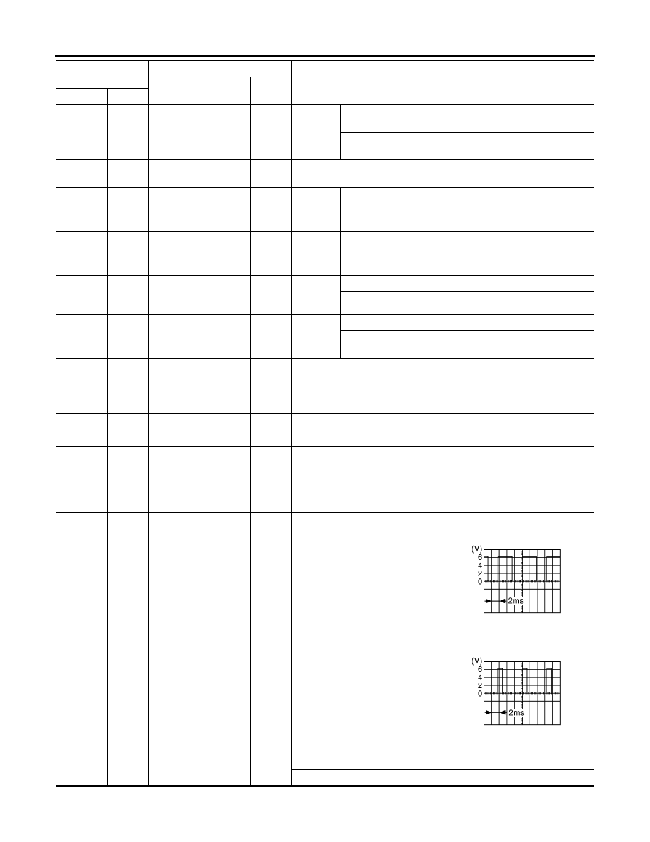
40 % is set on “ACTIVE TEST”, “AL-
TERNATOR DUTY” of “ENGINE”

3.8 V

80 % is set on “ACTIVE TEST”, “AL-
TERNATOR DUTY” of “ENGINE”

1.4 V

34

(R)

Ground

Horn relay control

Output

The horn is deactivated

Battery voltage

The horn is activated

0 V

Terminal NO.

(Wire color)

Description

Condition

Value

(Approx.)

Signal name

Input/

Output

+

JPMIA0002GB

JPMIA0003GB

IPDM E/R (INTELLIGENT POWER DISTRIBUTION MODULE ENGINE ROOM)

EXL-159

< ECU DIAGNOSIS INFORMATION >

C

D

E

F

G

H

I

J

K

M

A

B

EXL

N

O

P

36

(O)

Ground

Parking lamp (LH)

Output

Ignition 
switch 
ON

Lighting switch OFF

0 V

Lighting switch 1ST

Battery voltage

37

(V)

Ground

Parking lamp (RH)

Output

Ignition 
switch 
ON

Lighting switch OFF

0 V

Lighting switch 1ST

Battery voltage

38

(G)

Ground

Tail lamp (RH) & illumi-
nations

Output

Ignition 
switch 
ON

Lighting switch OFF

0 V

Lighting switch 1ST

Battery voltage

39

(V)

Ground

Front wiper HI

Output

Ignition 
switch 
ON

Front wiper switch OFF

0 V

Front wiper switch HI

Battery voltage

40

(R)

Ground

ECM relay control

Output

Ignition switch OFF
(More than a few seconds after turn-
ing ignition switch OFF)

Battery voltage

• Ignition switch ON
• Ignition switch OFF

(For a few seconds after turning ig-
nition switch OFF)

0 - 1.5 V

41

(SB)

Ground

Tail lamp (LH) & license 
plate lamps 

Output

Ignition 
switch 
ON

Lighting switch OFF

0 V

Lighting switch 1ST

Battery voltage

43

(G)

Ground

ECM relay power sup-
ply

Output

Ignition switch OFF
(More than a few seconds after turn-
ing ignition switch OFF)

0 V

• Ignition switch ON
• Ignition switch OFF

(For a few seconds after turning ig-
nition switch OFF)

Battery voltage

44

(P)

Ground

ECM relay power sup-
ply

Output

Ignition switch OFF
(More than a few seconds after turn-
ing ignition switch OFF)

0 V

• Ignition switch ON
• Ignition switch OFF

(For a few seconds after turning ig-
nition switch OFF)

Battery voltage

45

(Y)

Ground

TCM power supply

Output

Ignition switch OFF

Battery voltage

46

(O)

Ground

Front wiper LO

Output

Ignition 
switch 
ON

Front wiper switch OFF

0 V

Front wiper switch LO

Battery voltage

47

(BR)

Ground

Transmission range 

switch

*1

Input

Select lever in any position other than 
P or N (Ignition switch ON)

0 V

Select lever P or N (Ignition switch 
ON)

Battery voltage

Clutch interlock 

switch

*2

Release the clutch pedal

0 V

Depress the clutch pedal

Battery voltage

49

(W)

Ground

Headlamp HI (RH)

Output

Ignition 
switch 
ON

Lighting switch OFF

0 V

• Lighting switch HI
• Lighting switch PASS

Battery voltage

50

(GR)

Ground

Headlamp HI (LH)

Output

Ignition 
switch 
ON

Lighting switch OFF

0 V

• Lighting switch HI
• Lighting switch PASS

Battery voltage

Terminal NO.

(Wire color)

Description

Condition

Value

(Approx.)

Signal name

Input/

Output

+

EXL-160

< ECU DIAGNOSIS INFORMATION >

IPDM E/R (INTELLIGENT POWER DISTRIBUTION MODULE ENGINE ROOM)

*1: CVT models
*2: M/T models

51

(R)

Ground

Headlamp LO (LH)

Output

Ignition 
switch 
ON

Lighting switch OFF

0 V

Lighting switch 2ND

Battery voltage

52

(P)

Ground

Headlamp LO (RH)

Output

Ignition 
switch 
ON

Lighting switch OFF

0 V

Lighting switch 2ND

Battery voltage

54

(GR)

Ground

Throttle control motor 
relay power supply

Output

Ignition switch OFF
(More than a few seconds after turn-
ing ignition switch OFF)

0 V

• Ignition switch ON
• Ignition switch OFF

(For a few seconds after turning ig-
nition switch OFF)

Battery voltage

55

(P)

Ground

Fuel pump power sup-
ply

Output

Approximately 1 second or more than 
after turning the ignition switch ON

0 V

• Approximately 1 second after turn-

ing the ignition switch ON

• Engine running

Battery voltage

56

(SB)

Ground

A/C relay power supply

Output

Engine 
running

A/C switch OFF

0 V

A/C switch ON
(A/C compressor is oper-
ating)

Battery voltage

57

(G)

Ground

Throttle control motor 
relay control

Output

Ignition switch ON 

 OFF

0 - 1.0 V

Battery voltage

0 V

Ignition switch ON

0 - 1.0 V

58

(R)

Ground

Ignition relay power 
supply

Output

Ignition switch OFF

0 V

Ignition switch ON

Battery voltage

59

(Y)

Ground

Ignition relay power 
supply

Output

Ignition switch OFF

0 V

Ignition switch ON

Battery voltage

60

(V)

Ground

Ignition relay power 
supply

Output

Ignition switch OFF

0 V

Ignition switch ON

Battery voltage

61

(W)

Ground

Ignition relay power 
supply

Output

Ignition switch OFF

0 V

Ignition switch ON

Battery voltage

62

(L)

Ground

Ignition relay power 
supply

Output

Ignition switch OFF

0 V

Ignition switch ON

Battery voltage

64

*1

(R)

Ground

CVT shift selector
(Detention switch)

Input

Ignition 
switch 
ON

Select lever P

0 V

Select lever in any posi-
tion other than P

Battery voltage

66

(L)

Ground

Push-button ignition 
switch

Input

Press the push-button ignition switch

0 V

Release the push-button ignition 
switch

Battery voltage

69

(O)

Ground

Ignition relay monitor

Input

Ignition switch OFF or ACC

Battery voltage

Ignition switch ON

0 V

Terminal NO.

(Wire color)

Description

Condition

Value

(Approx.)

Signal name

Input/

Output

+

IPDM E/R (INTELLIGENT POWER DISTRIBUTION MODULE ENGINE ROOM)

EXL-161

< ECU DIAGNOSIS INFORMATION >

C

D

E

F

G

H

I

J

K

M

A

B

EXL

N

O

P

WITH INTELLIGENT KEY : Wiring Diagram — IPDM E/R —

INFOID:0000000010249368

JRMWE7720GB


Content   ..  469  470  471  472   ..