Nissan Cube. Manual - part 434
EXL-10
< SYSTEM DESCRIPTION >
AUTO LIGHT SYSTEM
NOTE:
As to ON/OFF timing, the sensitivity depends on settings. The settings can be changed with CONSULT. Refer
to
EXL-21, "HEADLAMP : CONSULT Function (BCM - HEAD LAMP)"
.
WIPER LINKED AUTO LIGHTING FUNCTION
BCM turns the exterior lamp ON when detecting 4 operations of the front wiper work the light switch in AUTO
position.
NOTE:
BCM turns OFF the headlamps 3 seconds after the front wiper switch is turned from HI
⇒
OFF.
DELAY TIMER FUNCTION
BCM turns the exterior lamp OFF depending on the vehicle condition with the auto light function when the igni-
tion switch is turned OFF.
• Turns the exterior lamp OFF 5 minutes after detecting that any door opens (Door switch ON).
• Turns the exterior lamp OFF a certain period of time* after closing all doors (Door switch ON
→
OFF).
• Turns the exterior lamp OFF with the ignition switch ACC or the light switch OFF.
*: The preset time is 45 seconds. The timer operating time can be set by CONSULT. Refer to
LAMP : CONSULT Function (BCM - HEAD LAMP)"
NOTE:
When any position other than the light switch AUTO is set, the auto light system function switches to the exte-
rior lamp battery saver function.
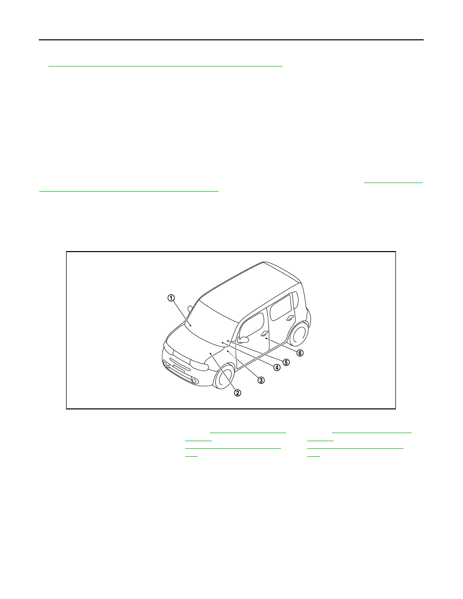
Component Parts Location
INFOID:0000000009945108
1.
Optical sensor
2.
IPDM E/R
Refer to
(with Intelligent Key) or
PCS-36, "Component Parts Loca-
tion"
(without Intelligent Key).
3.
BCM
Refer to
(with Intelligent Key) or
BCS-95, "Component Parts Loca-
tion"
(without Intelligent Key).
4.
Combination meter
5.
Combination switch
6.
Door switch
JPLIA1800ZZ