Nissan Cube. Manual - part 431
EXHAUST SYSTEM
EX-5
< REMOVAL AND INSTALLATION >
C
D
E
F
G
H
I
J
K
L
M
A
EX
N
P
O
REMOVAL AND INSTALLATION
EXHAUST SYSTEM
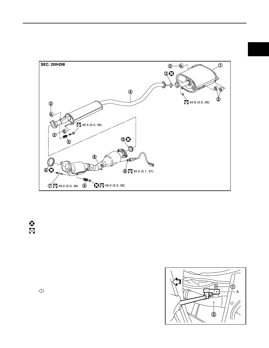
Exploded View
INFOID:0000000009948777
Removal and Installation
INFOID:0000000009948778
REMOVAL
• Disconnect each joint and mounting.
• Remove heated oxygen sensor 2 with following procedure:
- Using heated oxygen sensor wrench [SST: KV10114400 (J-
38365)] (A), removal heated oxygen sensor 2 (1).
CAUTION:
• Discard any heated oxygen sensor which has been dropped
from a height of more than 0.5 m (19.7 in) onto a hard sur-
face such as a concrete floor; use a new one.
• Before installing new heated oxygen sensor, clean exhaust
system threads using Oxygen Sensor Thread Cleaner (com-
mercial service tool) and approved Anti-seize lubricant (commercial servicetool).
1.
Main muffler
2.
Mounting rubber
3.
Ring gasket
4.
Center muffler
5.
Spring
6.
Seal bearing
7.
Stud bolt
8.
Exhaust front tube
9.
Heated oxygen sensor 2
10. Seal bearing
: Always replace after every disassembly.
: N·m (kg-m, ft-lb)
JPBIA2879GB
2
: Exhaust front tube
: Vehicle front
JPBIA2880ZZ