Nissan Cube. Manual - part 416


  Index      Nissan     Nissan Cube (2014 year) - Service and Repair Manual


Search            


Content   ..  414  415  416  417   ..


Nissan Cube. Manual - part 416


EM-68

< REMOVAL AND INSTALLATION >

CYLINDER HEAD

3.

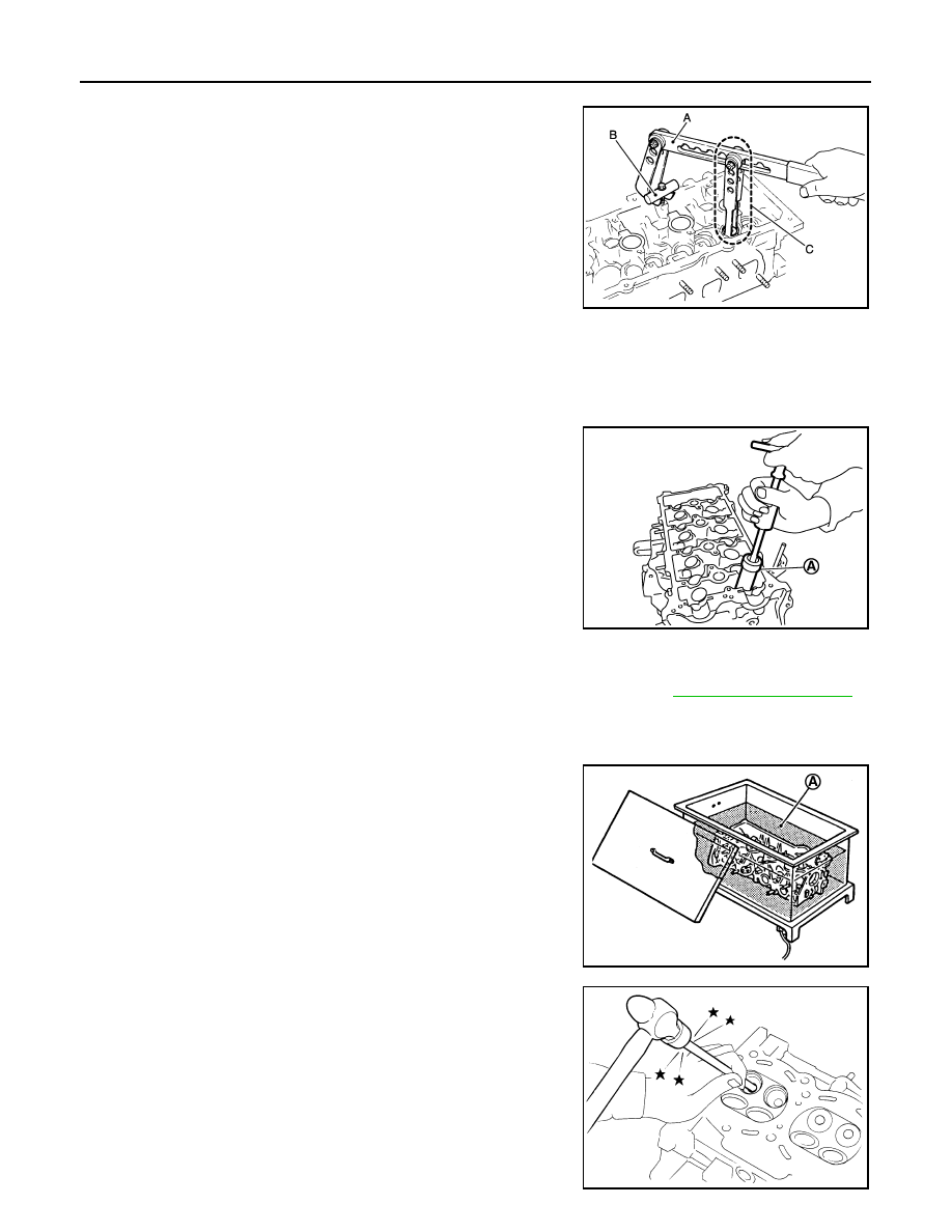
Remove valve collet. 
• Compress valve spring with the valve spring compressor [SST:

KV10116200 (J-26336-A)] (A), the attachment [SST:
KV10115900 (J-26336-20)] (C), and the adapter [SST:
KV10109220 (

)] (B). Remove valve collet with a magnet

hand.

CAUTION:

Be careful not to damage valve lifter holes.

4.

Remove valve spring retainer and valve spring (with valve spring seat).

CAUTION:

Never remove valve spring seat from valve spring.

5.

Push valve stem to combustion chamber side, and remove valve. 
• Identify installation positions, and store them without mixing them up.

6.

Remove valve oil seal with a valve oil seal puller [SST:
KV10107902 (J-38959)] (A).

7.

When valve seat must be replaced.
• Bore out old seat until it collapses. Boring should not continue beyond the bottom face of the seat

recess in cylinder head. Set the machine depth stop to ensure this. Refer to 

EM-116, "Cylinder Head"

.

CAUTION:

Never bore excessively to prevent cylinder head from scratching.

8.

When valve guide must be replaced.

a.

To remove valve guide, heat cylinder head to 110 to 130

°

C (230

to 266

°

F) by soaking in heated oil (A).

b.

Drive out valve guide with a hammer and valve guide drift (com-
mercial service tool).

CAUTION:

Cylinder head contains heat, wear protective equipment to
avoid getting burned.

JPBIA1365ZZ

PBIC3210J

PBIC3214J

SEM931C

CYLINDER HEAD

EM-69

< REMOVAL AND INSTALLATION >

C

D

E

F

G

H

I

J

K

L

M

A

EM

N

P

O

ASSEMBLY

1.

When valve guide is removed, install it. 

CAUTION:

Replace with oversize [0.2 mm (0.008 in)] valve guide.

a.

Ream cylinder head valve guide hole with a valve guide reamer
(commercial service tool) (A).

b.

Heat cylinder head to 110 to 130

°

C (230 to 266

°

F) by soaking in

heated oil (A).

c.

Press valve guide (1) from camshaft side to dimensions as
shown in the figure.

CAUTION:

Cylinder head contains heat, wear protective equipment to
avoid getting burned.

d.

Apply reamer finish to valve guide with a valve guide reamer
(commercial service tool) (A).

2.

When valve seat is removed, install it. 

CAUTION:

Replace with oversize [0.5 mm (0.020 in)] valve seat.

For service parts: Oversize [0.2 mm (0.008 in)] 

Refer to 

EM-116, "Cylinder Head"

.

PBIC3215J

PBIC3214J

2

: Cylinder head

Projection (H)

: Refer to 

EM-116, "Cylinder Head"

.

PBIC3217J

Standard

: Refer to 

EM-116, "Cylinder Head"

.

PBIC3215J

EM-70

< REMOVAL AND INSTALLATION >

CYLINDER HEAD

a.

Ream cylinder head (1) recess diameter for service valve seat
(2).

• Be sure to ream in circles concentric to the valve guide center.

This will enable valve seat to fit correctly.

b.

Heat cylinder head to 110 to 130

°

C (230 to 266

°

F) by soaking in

heated oil (A).

c.

Provide valve seats cooled well with dry ice. Press-fit valve seat into cylinder head.

CAUTION:

• Never touch cold valve seats directly.
• Cylinder head contains heat, wear protective equipment to avoid getting burned.

d.

Using valve seat cutter set (commercial service tool) or valve
seat grinder, finish valve seat to the specified dimensions. For
dimensions, refer to 

EM-116, "Cylinder Head"

.

CAUTION:

When using valve seat cutter, firmly grip the cutter handle
with both hands. Then, press on the contacting surface all
around the circumference to cut in a single drive. Improper
pressure on with the cutter or cutting many different times
may result in stage valve seat. 

e.

Using compound, grind to adjust valve fitting. 

f.

Check again for normal contact. Refer to 

EM-71, "Inspection"

.

3.

Install valve oil seal.
• Install with a valve oil seal drift [SST: KV10115600 (J-38958)]

(A) to match dimension in the figure.
NOTE:
Dimension is height that measured before installing valve
spring (with valve spring seat).

4.

Install valve.
• Install larger diameter to intake side.

5.

Install valve spring (with valve spring seat).

For service parts: Oversize [0.5 mm (0.020 in)]

Refer to 

EM-116, "Cylinder Head"

.

PBIC3218J

PBIC3214J

SEM934C

Height (H)

: 15.1 - 15.7 mm (0.594 - 0.618 in)

PBIC3211J

CYLINDER HEAD

EM-71

< REMOVAL AND INSTALLATION >

C

D

E

F

G

H

I

J

K

L

M

A

EM

N

P

O

• Install smaller pitch (valve spring seat side) to cylinder head

side (B).

• Confirm identification color (A) of valve spring.

6.

Install valve spring retainer.

7.

Install valve collet.
• Compress valve spring with the valve spring compressor [SST:

KV10116200 (J-26336-A)] (A), the attachment [SST:
KV10115900 (J-26336-20)] (C), and the adapter [SST:
KV10109220 (

)] (B). Install valve collet with a magnet

hand.

CAUTION:

When working care not to damage valve lifter holes.

• Tap valve stem edge lightly with a plastic hammer after instal-

lation to check its installed condition.

8.

Install valve lifter.
• Install it in the original position.

9.

Install spark plug with spark plug wrench (commercial service tool).

Inspection

INFOID:0000000009944957

INSPECTION AFTER REMOVAL

Cylinder Head Bolts Outer Diameter

• Cylinder head bolts are tightened by plastic zone tightening

method. Whenever the size difference between (d1) and (d2)
exceeds the limit, replace them with a new one. 

• If reduction of outer diameter appears in a position other than (d2),

use it as (d2) point.

Cylinder Head Distortion

NOTE:
When performing this inspection, cylinder block distortion should be also checked. Refer to 

EM-95, "Inspec-

tion"

.

1.

Wipe off engine oil and remove water scale (like deposit), gasket, sealant, carbon, etc. with a scraper.

CAUTION:

Never allow gasket debris to enter passages for engine oil or water.

1

: Valve spring seat (Do not remove from valve spring.)

Intake

: White

Exhaust

: Orange

PBIC3462J

JPBIA1365ZZ

Limit [(d1) – (d2)]: 0.15 mm (0.0059 in)

PBIC3994E


Content   ..  414  415  416  417   ..