Nissan Cube. Manual - part 347


  Index      Nissan     Nissan Cube (2014 year) - Service and Repair Manual


Search            


Content   ..  345  346  347  348   ..


Nissan Cube. Manual - part 347


EC-274

< DTC/CIRCUIT DIAGNOSIS >

[MR18DE]

P0448 EVAP CANISTER VENT CONTROL VALVE

Check the following.
• EVAP canister for damage
• EVAP hose between EVAP canister and vehicle frame for clogging or poor connection

>> Repair hose or replace EVAP canister. Refer to 

FL-14, "Exploded View"

.

6.

CHECK EVAP CONTROL SYSTEM PRESSURE SENSOR CONNECTOR

1.

Disconnect EVAP control system pressure sensor harness connector.

2.

Check connectors for water.

Is the inspection result normal?

YES

>> GO TO 7.

NO

>> Replace EVAP control system pressure sensor.

7.

CHECK EVAP CONTROL SYSTEM PRESSURE SENSOR

Refer to 

EC-279, "Component Inspection"

.

Is the inspection result normal?

YES

>> GO TO 8.

NO

>> Replace EVAP control system pressure sensor.

8.

CHECK INTERMITTENT INCIDENT

Refer to 

GI-40, "Intermittent Incident"

.

>> INSPECTION END

Component Inspection

INFOID:0000000009947388
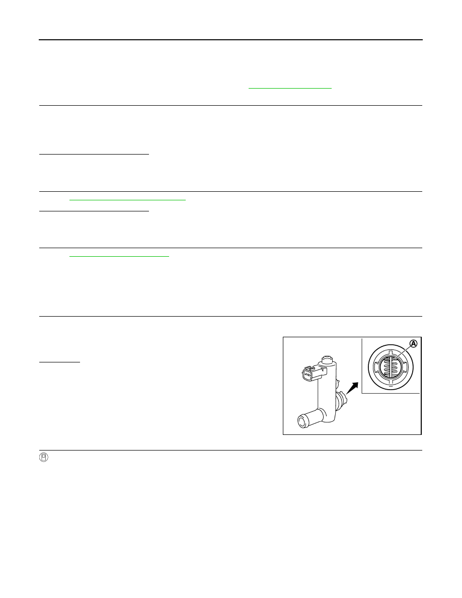
1.

CHECK EVAP CANISTER VENT CONTROL VALVE-I

1.

Turn ignition switch OFF.

2.

Remove EVAP canister vent control valve from EVAP canister.

3.

Check portion (A) of EVAP canister vent control valve for being
rusted.

Is it rusted?

YES

>> Replace EVAP canister vent control valve.

NO

>> GO TO 2.

2.

CHECK EVAP CANISTER VENT CONTROL VALVE-II

With CONSULT

1.

Reconnect harness connectors disconnected.

2.

Turn ignition switch ON.

3.

Perform “VENT CONTROL/V” in “ACTIVE TEST” mode.

Water should not exist.

JMBIA0168ZZ

P0448 EVAP CANISTER VENT CONTROL VALVE

EC-275

< DTC/CIRCUIT DIAGNOSIS >

[MR18DE]

C

D

E

F

G

H

I

J

K

L

M

A

EC

N

P

O

4.

Check air passage continuity and operation delay time.
Make sure new O-ring is installed properly.

Operation takes less than 1 second.

Without CONSULT

Check air passage continuity and operation delay time under the fol-
lowing conditions.
Make sure new O-ring is installed properly.

Operation takes less than 1 second.

Is the inspection result normal?

YES

>> GO TO 3.

NO

>> Replace EVAP canister vent control valve.

3.

CHECK EVAP CANISTER VENT CONTROL VALVE-III

With CONSULT

1.

Clean the air passage [portion (A) to (B)] of EVAP canister vent control valve using an air blower.

2.

Perform “VENT CONTROL/V” in “ACTIVE TEST” mode.

3.

Check air passage continuity and operation delay time.
Make sure new O-ring is installed properly.

Operation takes less than 1 second.

Without CONSULT

1.

Clean the air passage [portion (A) to (B)] of EVAP canister vent
control valve using an air blower.

2.

Check air passage continuity and operation delay time under the
following conditions.
Make sure new O-ring is installed properly.

Operation takes less than 1 second.

Is the inspection result normal?

YES

>> INSPECTION END

NO

>> Replace EVAP canister vent control valve.

VENT CONT/V condition

Air passage continuity between (A) and (B)

ON

Not existed

OFF

Existed

Condition

Air passage continuity between (A) and (B)

12 V direct current supply between 
terminals (1) and (2)

Not existed

OFF

Existed

JMBIA0169ZZ

VENT CONT/V condition 

Air passage continuity between (A) and (B)

ON

Not existed

OFF

Existed

Condition

Air passage continuity between (A) and (B)

12 V direct current supply between
 terminals (1) and (2)

Not existed

OFF

Existed

JMBIA0169ZZ

EC-276

< DTC/CIRCUIT DIAGNOSIS >

[MR18DE]

P0451 EVAP CONTROL SYSTEM PRESSURE SENSOR

P0451 EVAP CONTROL SYSTEM PRESSURE SENSOR

Description

INFOID:0000000009947389

The EVAP control system pressure sensor detects pressure in the
purge line. The sensor output voltage to the ECM increases as pres-
sure increases.

DTC Logic

INFOID:0000000009947390

DTC DETECTION LOGIC

DTC CONFIRMATION PROCEDURE

NOTE:
Never remove fuel filler cap during DTC confirmation procedure.

1.

PRECONDITIONING

If DTC Confirmation Procedure has been previously conducted, always turn ignition switch OFF and wait at
least 10 seconds before conducting the next test.

With CONSULT>>GO TO 2.
Without CONSULT>>GO TO 5.

2.

PERFORM DTC CONFIRMATION PROCEDURE-1

With CONSULT

1.

Start engine and let it idle for least 40 seconds.
NOTE:
Do not depress accelerator pedal even slightly.

2.

Check 1st trip DTC.

Is 1st trip DTC detected?

YES

>> Proceed to 

EC-277, "Diagnosis Procedure"

.

NO

>> GO TO 3.

3.

PERFORM DTC CONFIRMATION PROCEDURE-2

PBIB3370E

DTC No.

Trouble diagnosis name

DTC detecting condition

Possible cause

P0451

EVAP control system 
pressure sensor perfor-
mance

ECM detects a sloshing signal from the EVAP 
control system pressure sensor

• Harness or connectors

(EVAP control system pressure sensor 
circuit is shorted.)
[Crankshaft position sensor (POS) circuit 
is shorted.]
(Accelerator pedal position sensor circuit 
is shorted.)
(Refrigerant pressure sensor circuit is 
shorted.)
(Battery current sensor circuit is shorted.)

• EVAP control system pressure sensor
• Crankshaft position sensor (POS)
• Accelerator pedal position sensor
• Refrigerant pressure sensor
• Battery current sensor

P0451 EVAP CONTROL SYSTEM PRESSURE SENSOR

EC-277

< DTC/CIRCUIT DIAGNOSIS >

[MR18DE]

C

D

E

F

G

H

I

J

K

L

M

A

EC

N

P

O

With CONSULT

1.

Select “EVAP DIAG READY” in “DATA MONITOR” mode of “ENGINE”.

2.

Let it idle until “OFF” of “EVAP DIAG READY” changes to “ON”.
NOTE:
It will take at most 2 hours until “OFF” of “EVAP DIAG READY” changes to “ON”.

3.

Turn ignition switch OFF and wait at least 90 minutes.
NOTE:
Never turn ignition switch ON during 90 minutes.

4.

Turn ignition switch ON.

5.

Select “EVAP LEAK DIAG” in “DATA MONITOR” mode of “ENGINE”.

6.

Check that “EVAP LEAK DIAG” indication.

Which is displayed on CONSULT?

CMPLT >> GO TO 4.
YET

>> 1.

Perform DTC CONFIRMATION PROCEDURE again.

2.

GO TO 1.

4.

PERFORM DTC CONFIRMATION PROCEDURE-3

With CONSULT

Check 1st trip DTC.

Is 1st trip DTC detected?

YES

>> Proceed to 

EC-277, "Diagnosis Procedure"

.

NO

>> INSPECTION END

5.

PERFORM DTC CONFIRMATION PROCEDURE-4

With GST

1.

Start engine and let it idle for least 40 seconds.
NOTE:
Do not depress accelerator pedal even slightly.

2.

Check 1st trip DTC.

Is 1st trip DTC detected?

YES

>> Proceed to 

EC-277, "Diagnosis Procedure"

.

NO

>> GO TO 6.

6.

PERFORM DTC CONFIRMATION PROCEDURE-5

With GST

1.

Let it idle for at least 2 hours.

2.

Turn ignition switch OFF and wait at least 90 minutes.
NOTE:
Never turn ignition switch ON during 90 minutes.

3.

Turn ignition switch ON.

4.

Check 1st trip DTC.

Is 1st trip DTC detected?

YES

>> Proceed to 

EC-277, "Diagnosis Procedure"

.

NO

>> INSPECTION END

Diagnosis Procedure

INFOID:0000000009947391

1.

CHECK GROUND CONNECTION

1.

Turn ignition switch OFF.

2.

Check ground connection E38. Refer to 

GI-43, "Circuit Inspection"

.

Is the inspection result normal?

YES

>> GO TO 2.

NO

>> Repair or replace ground connection.

2.

CHECK EVAP CONTROL SYSTEM PRESSURE SENSOR CONNECTOR FOR WATER

1.

Disconnect EVAP control system pressure sensor harness connector.

2.

Check sensor harness connector for water.


Content   ..  345  346  347  348   ..