Nissan Cube. Manual - part 311
EC-130
< DTC/CIRCUIT DIAGNOSIS >
[MR18DE]
POWER SUPPLY AND GROUND CIRCUIT
6.
CHECK ECM POWER SUPPLY CIRCUIT-II
1.
Turn ignition switch OFF and wait at least 10 seconds.
2.
Turn ignition switch ON and then OFF.
3.
Check the voltage between ECM harness connector and ground.
Is the inspection result normal?
YES
>> GO TO 7.
NO
>> GO TO 9.
7.
CHECK ECM POWER SUPPLY CIRCUIT-III
1.
Turn ignition switch ON.
2.
Check the voltage between IPDM E/R harness connector and ground.
Is the inspection result normal?
YES
>> GO TO 8.
NO
>> Replace IPDM E/R. Refer to
PCS-34, "Removal and Installation"
(With I-KEY) or
(Without I-KEY).
8.
CHECK INTERMITTENT INCIDENT
GI-40, "Intermittent Incident"
>> INSPECTION END
9.
CHECK ECM POWER SUPPLY CIRCUIT-IV
1.
Turn ignition switch OFF and wait at least 10 seconds.
2.
Check the voltage between ECM harness connector and ground.
Is the inspection result normal?
YES
>> GO TO 13.
NO
>> GO TO 10.
10.
CHECK ECM POWER SUPPLY CIRCUIT-V
1.
Disconnect ECM harness connector.
2.
Disconnect IPDM E/R harness connector E14.
3.
Check the continuity between ECM harness connector and IPDM E/R harness connector.
4.
Also check harness for short to ground and short to power.
Is the inspection result normal?
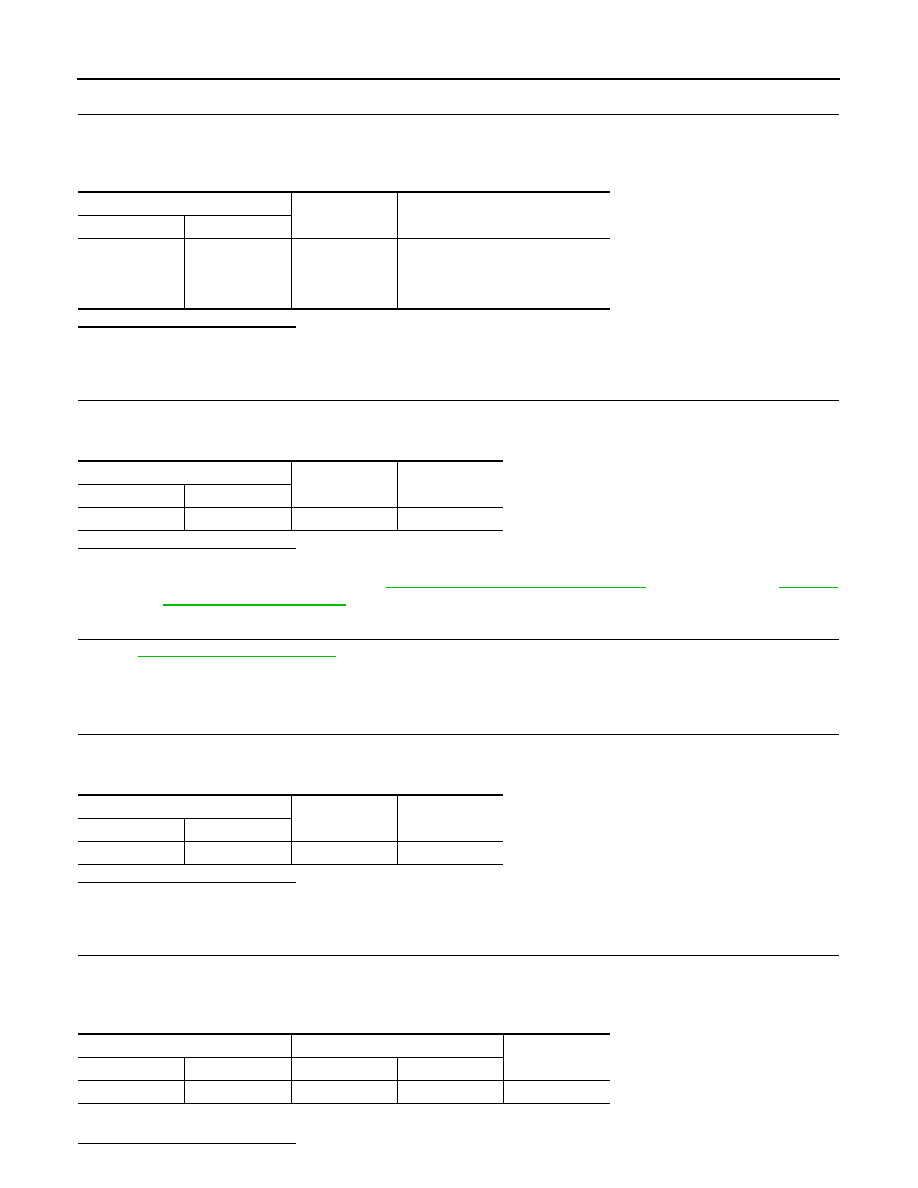
ECM
Ground
Voltage
Connector
Terminal
E16
105
Ground
After turning ignition switch OFF,
battery voltage will exist for a few
seconds, then drop approximately 0
V.
IPDM E/R
Ground
Voltage
Connector
Terminal
E14
44
Ground
Battery voltage
ECM
Ground
Voltage
Connector
Terminal
F7
32
Ground
Battery voltage
ECM
IPDM E/R
Continuity
Connector
Terminal
Connector
Terminal
F7
32
E14
40
Existed