Nissan Cube. Manual - part 301
EC-90
< SYSTEM DESCRIPTION >
[MR18DE]
EVAPORATIVE EMISSION SYSTEM
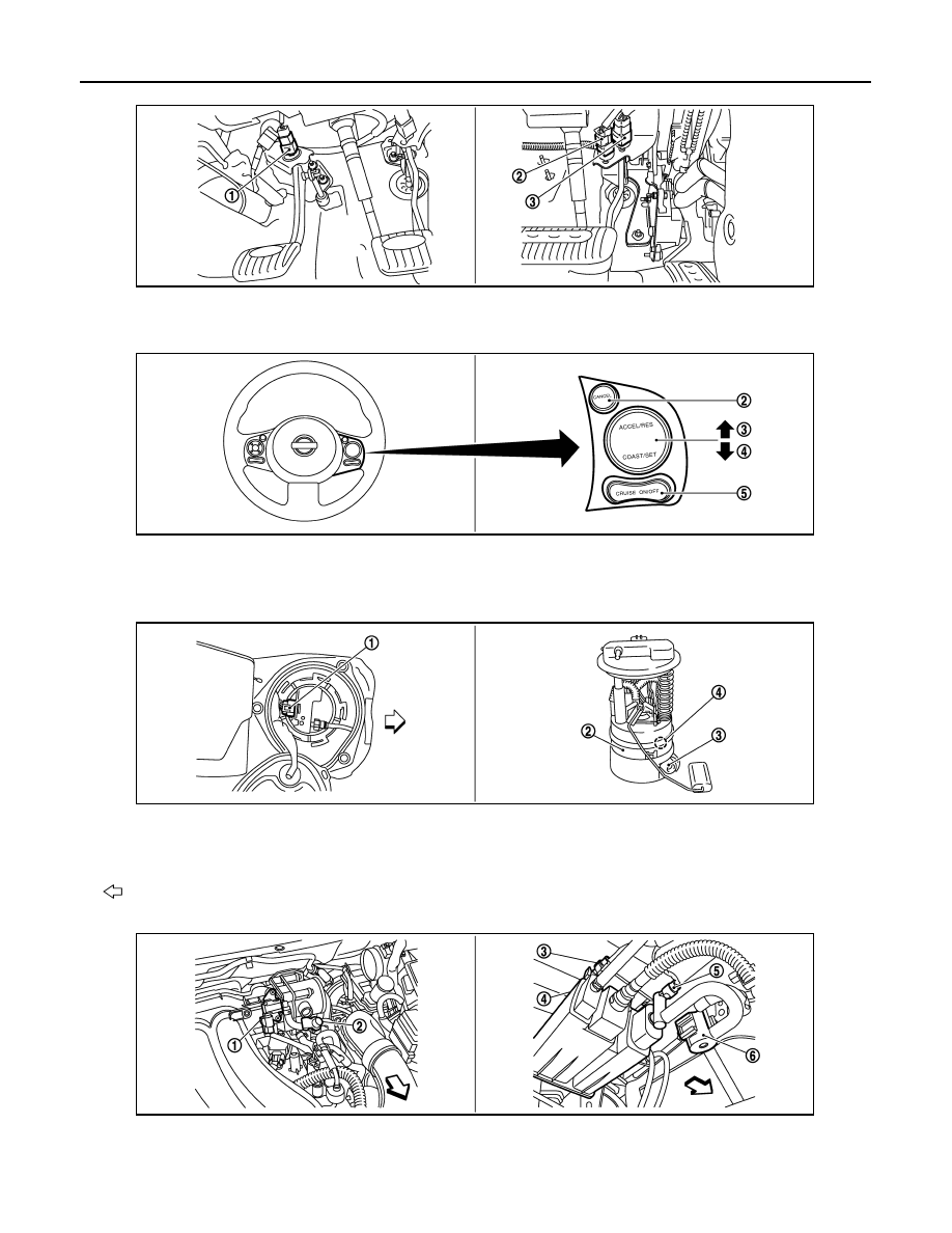
1.
ASCD clutch switch
2.
ASCD brake switch
3.
Stop lamp switch
1.
ASCD steering switch
2.
CANCEL switch
3.
RESUME/ACCELERATE switch
4.
SET/COST switch
5.
MAIN switch
1.
Fuel level sensor unit and fuel pump
harness connector
2.
Fuel level sensor unit and fuel pump 3.
Fuel pressure regulator
4.
Fuel tank temperature sensor
Vehicle front
1.
EVAP canister purge volume control
solenoid valve
2.
EVAP service port
3.
EVAP control system pressure sen-
sor
JMBIA2307ZZ
JMBIA2308ZZ
JMBIA2309ZZ
JMBIA2310ZZ