Nissan Cube. Manual - part 267


  Index      Nissan     Nissan Cube (2014 year) - Service and Repair Manual


Search            


Content   ..  265  266  267  268   ..


Nissan Cube. Manual - part 267


DLK-334

< REMOVAL AND INSTALLATION >

[WITHOUT INTELLIGENT KEY SYSTEM]

HOOD

REMOVAL AND INSTALLATION

HOOD

HOOD ASSEMBLY

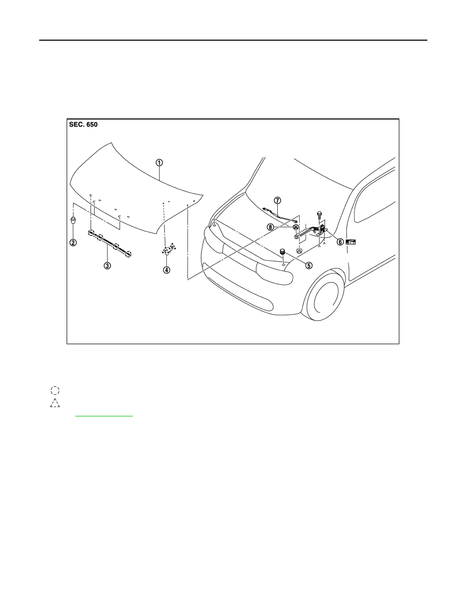
HOOD ASSEMBLY : Exploded View

INFOID:0000000009950773

HOOD ASSEMBLY : Removal and Installation

INFOID:0000000009950774

REMOVAL

1.

Support hood lock assembly with the proper material to prevent it from falling.

WARNING:

Bodily injury may occur if no supporting rod is holding hood open when removing hood stay.

2.

Remove hood hinge mounting nuts on the hood to remove the hood assembly.

CAUTION:

Perform work with 2 workers, because of its heavy weight.

INSTALLATION

Install in the reverse order of removal.

CAUTION:

• Perform work with 2 workers, because of its heavy weight.
• Check hood hinge rotating part for poor lubrication. If necessary, apply body grease. 
• After installation, apply touch-up paint (the body color) onto the heads of hood hinge mounting bolts

and nuts. 

1.

Hood assembly

2.

Hood bumper rubber (hood side)

3.

Radiator core seal

4.

Clamp

5.

Hood bumper rubber (body side)

6.

Hood hinge

7.

Hood support rod

8.

Grommet

 : Clip

 : Pawl

Refer to 

GI-4, "Components"

 for symbols in the figure.

JMKIA3624ZZ

HOOD

DLK-335

< REMOVAL AND INSTALLATION >

[WITHOUT INTELLIGENT KEY SYSTEM]

C

D

E

F

G

H

I

J

L

M

A

B

DLK

N

O

P

• After installing, perform hood fitting adjustment. Refer to 

DLK-335, "HOOD ASSEMBLY : Adjust-

ment"

.

HOOD ASSEMBLY : Adjustment

INFOID:0000000009950775

Check the clearance and the surface height between hood and each part by visually and touching.
If the clearance and the surface height are out of specification, adjust them according to the procedures
shown below.

Unit: mm (in)

1.

Hood assembly

2.

Hood bumper rubber 

3.

Hood hinge

4.

Hood lock assembly

5.

Front grille

6.

Front combination lamp

7.

Front fender

Refer to 

GI-4, "Components"

 for symbols in the figure.

Portion

Standard

Difference

(RH/LH)

Hood – Front grille

A – A D

Clearance

6.0 – 10.0 (0.236 – 0.394)

< 2.0 (0.079)

Hood – Front combination lamp B – B E

Clearance

6.0 – 10.0 (0.236 – 0.394)

< 2.0 (0.079)

Hood – Front fender

C – C

F

Clearance

2.5 – 4.5 (0.098 – 0.177)

< 1.0 (0.039)

G Surface height - 1.0 – 1.0 (- 0.039 – 0.039)

JMKIA3826GB

DLK-336

< REMOVAL AND INSTALLATION >

[WITHOUT INTELLIGENT KEY SYSTEM]

HOOD

1.

Remove hood lock and adjust the surface height of hood, front grill and front fender according to the fitting
standard dimension, by rotating hood bumper rubber (body side).

2.

Loosen hood hinge mounting nuts on the hood.

3.

Check that hood lock primary latch is securely engaged with striker by dropping hood from approximately
200 mm (7.874 in) height or by pressing lightly on the hood.

CAUTION:

Never drop hood from a height of 300 mm (11.811 in) or more

4.

Install as static closing face of hood is 94– 490 N (9.6 – 50.0 kg, 21.1 – 110 lb).

5.

After adjustment tighten lock bolts to the specified torque.

CAUTION:

• Check hood hinge rotating part for poor lubrication. If necessary, apply body grease.
• After installation, apply touch-up paint (the body color) onto the heads of hood hinge mounting bolts

and nuts.

HOOD HINGE

HOOD HINGE : Exploded View

INFOID:0000000009950776

HOOD HINGE : Removal and Installation

INFOID:0000000009950777

REMOVAL

1.

Remove hood assembly. Refer to 

DLK-334, "HOOD ASSEMBLY : Removal and Installation"

.

2.

Remove front fender. Refer to 

DLK-341, "Removal and Installation"

.

1.

Hood assembly

2.

Hood bumper rubber (hood side)

3.

Radiator core seal

4.

Clamp

5.

Hood bumper rubber (body side)

6.

Hood hinge

7.

Hood support rod

8.

Grommet

 : Clip

 : Pawl

Refer to 

GI-4, "Components"

 for symbols in the figure.

JMKIA3624ZZ

HOOD

DLK-337

< REMOVAL AND INSTALLATION >

[WITHOUT INTELLIGENT KEY SYSTEM]

C

D

E

F

G

H

I

J

L

M

A

B

DLK

N

O

P

3.

Remove cowl top. Refer to 

EXT-19, "Removal and Installation"

4.

Remove hood hinge mounting bolts, and then remove hood hinge.

INSTALLATION

Install in the reverse order of removal.

CAUTION:

• Check hood hinge rotating part for poor lubrication. If necessary, apply grease.
• After installation, apply touch-up paint (the body color) onto the head of the hinge mounting bolts

and nuts.

• After installation, perform hood fitting adjustment. Refer to 

DLK-335, "HOOD ASSEMBLY : Adjust-

ment"

.

HOOD SUPPORT ROD

HOOD SUPPORT ROD : Exploded View

INFOID:0000000009950778

HOOD SUPPORT ROD : Removal and Installation

INFOID:0000000009950779

REMOVAL

1.

Support hood assembly with a suitable material to prevent it from falling.

WARNING:

Bodily injury may occur if no supporting rod is holding the hood open when removing the hood
support rod.

2.

Pull hood support rod from grommet and remove.

1.

Hood assembly

2.

Hood bumper rubber (hood side)

3.

Radiator core seal

4.

Clamp

5.

Hood bumper rubber (body side)

6.

Hood hinge

7.

Hood support rod

8.

Grommet

 : Clip

 : Pawl

Refer to 

GI-4, "Components"

 for symbols in the figure.

JMKIA3624ZZ


Content   ..  265  266  267  268   ..