Nissan Cube. Manual - part 215
DLK-126
< ECU DIAGNOSIS INFORMATION >
[WITH INTELLIGENT KEY SYSTEM]
BCM (BODY CONTROL MODULE)
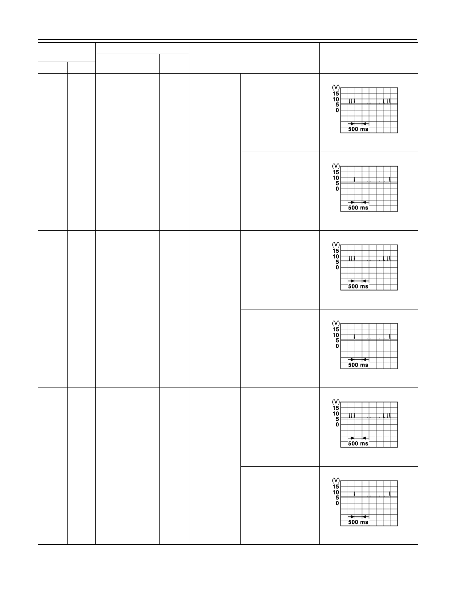
80
(BR/Y)
Ground
Passenger door an-
tenna (+)
Output
When the pas-
senger door re-
quest switch is
operated with
ignition switch
ON
When Intelligent Key is
not in the antenna detec-
tion area
(The distance between In-
telligent Key and antenna:
Approx. 2 m)
When Intelligent Key is in
the antenna detection
area
(The distance between In-
telligent Key and antenna:
80 cm or less)
81
(L/Y)
Ground
Passenger door an-
tenna (-)
Output
When the pas-
senger door re-
quest switch is
operated with
ignition switch
ON
When Intelligent Key is
not in the antenna detec-
tion area
(The distance between In-
telligent Key and antenna:
Approx. 2 m)
When Intelligent Key is in
the antenna detection
area
(The distance between In-
telligent Key and antenna:
80 cm or less)
82
(W/B)
Ground
Back door antenna
(+)
Output
When the back
door request
switch is operat-
ed with ignition
switch ON
When Intelligent Key is
not in the antenna detec-
tion area
(The distance between In-
telligent Key and antenna:
Approx. 2 m)
When Intelligent Key is in
the antenna detection
area
(The distance between In-
telligent Key and antenna:
80 cm or less)
Terminal No.
(Wire color)
Description
Condition
Value
(Approx.)
Signal name
Input/
Output
+
−
JMKIA5954GB
JMKIA5955GB
JMKIA5954GB
JMKIA5955GB
JMKIA5954GB
JMKIA5955GB