Content .. 1066 1067 1068 1069 ..
Nissan Cube. Manual - part 1068
BCM (BODY CONTROL MODULE)
WW-109
< ECU DIAGNOSIS INFORMATION >
C
D
E
F
G
H
I
J
K
M
A
B
WW
N
O
P
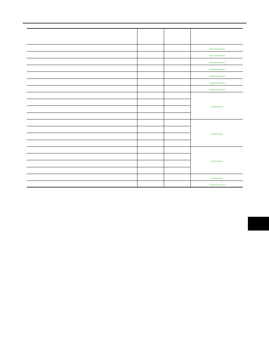
CONSULT display
Fail-safe
Tire pressure
monitor warn-
ing lamp ON
Reference
U1000: CAN COMM
—
—
U1010: CONTROL UNIT (CAN)
—
—
B2190: NATS ANTENNA AMP
×
—
B2191: DIFFERENCE OF KEY
×
—
B2192: ID DISCORD BCM-ECM
×
—
B2193: CHAIN OF BCM-ECM
×
—
B2195: ANTI SCANNING
×
—
C1704: LOW PRESSURE FL
—
×
C1705: LOW PRESSURE FR
—
×
C1706: LOW PRESSURE RR
—
×
C1707: LOW PRESSURE RL
—
×
C1708: [NO DATA] FL
—
×
C1709: [NO DATA] FR
—
×
C1710: [NO DATA] RR
—
×
C1711: [NO DATA] RL
—
×
C1716: [PRESS DATA ERR] FL
—
×
C1717: [PRESS DATA ERR] FR
—
×
C1718: [PRESS DATA ERR] RR
—
×
C1719: [PRESS DATA ERR] RL
—
×
C1729: VHCL SPEED SIG ERR
—
×
C1735: IGN CIRCUIT OPEN
—
—