Nissan Cube. Manual - part 97
BRC-38
< DTC/CIRCUIT DIAGNOSIS >
[VDC/TCS/ABS]
C1110, C1153, C1170 ABS ACTUATOR AND ELECTRIC UNIT (CONTROL UNIT)
C1110, C1153, C1170 ABS ACTUATOR AND ELECTRIC UNIT (CONTROL
UNIT)
DTC Logic
INFOID:0000000009949931
DTC DETECTION LOGIC
DTC CONFIRMATION PROCEDURE
1.
PRECONDITIONING
If “DTC CONFIRMATION PROCEDURE” has been previously conducted, always turn ignition switch OFF and
wait at least 10 seconds before conducting the next test.
>> GO TO 2.
2.
DTC REPRODUCTION PROCEDURE
1.
Turn the ignition switch ON.
2.
Perform self-diagnosis for “ABS” with CONSULT.
Is DTC “C1110”, “C1153” or “C1170” detected?
YES
>> Proceed to diagnosis procedure. Refer to
.
NO
>> INSPECTION END
Diagnosis Procedure
INFOID:0000000009949932
1.
REPLACE ABS ACTUATOR AND ELECTRIC UNIT (CONTROL UNIT)
CAUTION:
Replace ABS actuator and electric unit (control unit) when self-diagnostic result shows items other
than those applicable.
>> Replace ABS actuator and electric unit (control unit). Refer to
.
Special Repair Requirement
INFOID:0000000009949933
1.
ADJUSTMENT OF STEERING ANGLE SENSOR NEUTRAL POSITION
Always perform the neutral position adjustment for the steering angle sensor, when replacing the ABS actua-
tor and electric unit (control unit) or steering angle sensor and removing steering angle sensor. Refer to
9, "Special Repair Requirement"
>> END
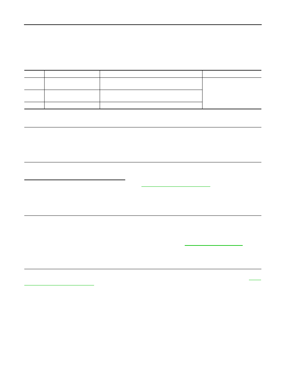
DTC
Display item
Malfunction detected condition
Possible cause
C1110
CONTROLLER FAILURE
When there is an internal malfunction in the ABS actuator
and electric unit (control unit).
ABS actuator and electric unit
(control unit)
C1153
EMERGENCY BRAKE
When ABS actuator and electric unit (control unit) is mal-
functioning. (Pressure increase is too much or too little)
C1170
VARIANT CODING
In a case where VARIANT CODING is different.